


P/N 89800, Rev. 2
Page 43
The gear of the electric drive is lubricated for lifetime, i.e. there is no need of addi-
tional lubrication.
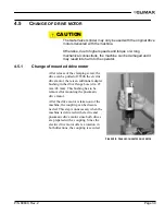
5.3.1
Pneumatic drive motor gear
The gear of the pneumatic drive motor has to be disassembled and cleaned after
150 working hours and then be lubricated with Bosch-special grease. This proce-
dure has to be repeated every 300 working hours. CLIMAX offers this service.
5.3.2
Drive chain
The drive chain integrated in the machine arm and the upper gear has to be
inspected every 500 working hours (after 1 year at the latest). For this inspection,
the cover of the upper gear has to be removed and the gears as well as the chain
have to be thoroughly lubricated with Tunap Tunfluid HT 2200.
After replacing the cover, the drive chain tension has to be adjusted.
We recommend having this service done by the manufacturer due to the experience
required.
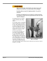
In case of a rattling noise coming out of the machine arm, most likely the drive
chain is not sufficient anymore. To adjust the tension of the drive chain, untie the
screws of the machine arm clamping plate 20T-021 and adjust the tension by
means of the adjusting screw 20N-026.
After every half rotation of the adjusting screw, check if the noise disappears. After
adjusting the tension of the drive chain, tighten the screws of the clamping plate.
After this procedure has been repeated several times, the chain will be stretched to
its limits and must be replaced.
5.3.3
Ball joint coupling
Before every machine operation, the ball joint coupling of the machine spindle
should be lubricated with grease. See the lubrication table.
5.4
L
UBRICATING THE PNEUMATIC DRIVE MOTOR
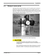
Make sure that the lubricator of the maintenance unit is always filled with oil. In
addition, make sure that the pneumatic drive motor is always operated with clean
air. Check the filter on the maintenance unit regularly.
Drain condenser water if required.
5.5
T
ROUBLESHOOTING
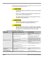
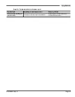
If the machine cannot be started or if there are any malfunctions during operation,
the operator has to inform qualified maintenance personnel immediately.
Summary of Contents for VM1350
Page 2: ......
Page 4: ...Page B VM1350 1500 1600 Operating Manual CLIMAX GLOBAL LOCATIONS ...
Page 5: ...P N 89800 Rev 2 Page C CE DOCUMENTATION ...
Page 12: ...Page vi VM1350 1500 1600 Operating Manual This page intentionally left blank ...
Page 18: ...Page 6 VM1350 1500 1600 Operating Manual This page intentionally left blank ...
Page 44: ...Page 32 VM1350 1500 1600 Operating Manual This page intentionally left blank ...
Page 58: ...Page 46 VM1350 1500 1600 Operating Manual This page intentionally left blank ...
Page 62: ...Page 50 VM1350 1500 1600 Operating Manual FIGURE A 1 GATE VALVE GRINDING AND LAPPING MACHINE ...
Page 63: ...P N 89800 Rev 2 Page 51 ...
Page 64: ...Page 52 VM1350 1500 1600 Operating Manual ...
Page 65: ...P N 89800 Rev 2 Page 53 FIGURE A 2 440 10S N01 00 BASIC MACHINE ...
Page 66: ...Page 54 VM1350 1500 1600 Operating Manual ...
Page 67: ...P N 89800 Rev 2 Page 55 FIGURE A 3 240 11S N01 00 ELECTRIC DRIVE ...
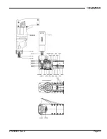
Page 68: ...Page 56 VM1350 1500 1600 Operating Manual FIGURE A 4 240 13S N01 00 PNEUMATIC DRIVE ...
Page 69: ...P N 89800 Rev 2 Page 57 FIGURE A 5 240 15S N01 00 ELECTRIC DRIVE 115 V ...
Page 70: ...Page 58 VM1350 1500 1600 Operating Manual FIGURE A 6 440 20S N01 00 UPPER GEAR ...
Page 71: ...P N 89800 Rev 2 Page 59 FIGURE A 7 440 21S N01 00 UPPER GEAR ADDITIONAL PARTS FOR T 1000 ...
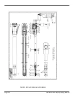
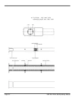
Page 73: ...P N 89800 Rev 2 Page 61 FIGURE A 9 440 33S N01 00 MACHINE ARM WITH SUBMERGING DEPTH T 800 ...
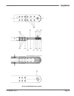
Page 75: ...P N 89800 Rev 2 Page 63 FIGURE A 11 440 35S N01 00 MACHINE ARM WITH SUBMERGING DEPTH T 1000 ...
Page 77: ...P N 89800 Rev 2 Page 65 FIGURE A 13 440 37S N01 00 MACHINE ARM GENERAL PARTS ...
Page 78: ...Page 66 VM1350 1500 1600 Operating Manual FIGURE A 14 440 40S N01 00 BALL JOINT ...
Page 79: ...P N 89800 Rev 2 Page 67 FIGURE A 15 440 41S N01 00 BALL JOINT TYPE 10 ...
Page 80: ...Page 68 VM1350 1500 1600 Operating Manual FIGURE A 16 170 30S N01 00 ...
Page 81: ...P N 89800 Rev 2 Page 69 FIGURE A 17 440 42S N01 00 BALL JOINT TYPE 15 ...
Page 82: ...Page 70 VM1350 1500 1600 Operating Manual FIGURE A 18 170 10S N01 00 ...
Page 83: ...P N 89800 Rev 2 Page 71 FIGURE A 19 MOUNTING SYSTEM ...
Page 84: ...Page 72 VM1350 1500 1600 Operating Manual FIGURE A 20 440 51S N01 00 TILTING ADAPTER ...
Page 85: ...P N 89800 Rev 2 Page 73 FIGURE A 21 440 52S N01 00 MOUNTING FOR VALVE BODIES WITH FLANGES ...
Page 86: ...Page 74 VM1350 1500 1600 Operating Manual ...
Page 87: ...P N 89800 Rev 2 Page 75 FIGURE A 22 440 53S N01 00 MOUNTING FOR VALVE BODIES WITHOUT FLANGES ...
Page 88: ...Page 76 VM1350 1500 1600 Operating Manual FIGURE A 23 440 55S N01 00 SWING CHECK ADAPTER ...
Page 90: ...Page 78 VM1350 1500 1600 Operating Manual Tooling ...
Page 91: ...P N 89800 Rev 2 Page 79 ...
Page 94: ...Page 82 VM1350 1500 1600 Operating Manual FIGURE A 27 110 20S N01 02 PLANET ARMS ...
Page 96: ...Page 84 VM1350 1500 1600 Operating Manual This page intentionally left blank ...
Page 97: ......
Page 98: ......