P/N 89800, Rev. 2
Page 11
3
SETUP
IN THIS CHAPTER:
3.1 R
ECEIPT AND INSPECTION
- - - - - - - - - - - - - - - - - - - - - - - - - - - - - - - - - - - - - 11
3.2 S
ELECTING AND PREPARING TOOLS
- - - - - - - - - - - - - - - - - - - - - - - - - - - - - - - - - 14
3.2.1 S
ELECTING TOOLS FOR PLANET WHEELS
DN 80–DN 600 - - - - - - - - - - - - - - - - - - - - 14
3.2.2 P
REPARING TOOLS FOR
DN 80–DN 600 - - - - - - - - - - - - - - - - - - - - - - - - - - - 16
3.2.3 S
ELECTING SOLID GRINDING DISCS FOR
DN 40–DN 65 - - - - - - - - - - - - - - - - - - - - - 17
3.3 M
OUNTING THE TILTING ADAPTER ON THE VALVE BODY
- - - - - - - - - - - - - - - - - - - - - - - - 18
3.3.1 M
OUNTING THE TILTING ADAPTER ON VALVES WITH FLANGE
- - - - - - - - - - - - - - - - - - - 19
3.3.2 C
OLLAR BAND MOUNTING
- - - - - - - - - - - - - - - - - - - - - - - - - - - - - - - - - - - 21
3.3.3 M
OUNTING THE BRACKET
- - - - - - - - - - - - - - - - - - - - - - - - - - - - - - - - - - - 24
3.3.4 M
OUNTING THE DRIVE SHAFT WITH BALL JOINT
- - - - - - - - - - - - - - - - - - - - - - - - - 24
3.3.5 A
DAPTATING THE PLANET WHEEL DIA
. 100
OR DIA
. 135 - - - - - - - - - - - - - - - - - - - - - 26
3.3.6 A
DAPTATING THE PLANET WHEEL DIA
. 220
MM OR BIGGER
- - - - - - - - - - - - - - - - - - - 26
3.3.7 A
DAPTATING THE SOLID GRINDING DISCS
- - - - - - - - - - - - - - - - - - - - - - - - - - - 27
3.4 L
OCATING AND ALIGNMENT OF MACHINE IN TILTING ADAPTER
- - - - - - - - - - - - - - - - - - - - - - 27
3.5 I
NSTALLATION
- - - - - - - - - - - - - - - - - - - - - - - - - - - - - - - - - - - - - - - - - - - 30
This section describes the setup and assembly procedures for the VM1350-1500-
1600 Gate Valve Grinding and Lapping Machine.
3.1
R
ECEIPT AND INSPECTION
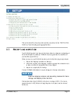
Your CLIMAX product was inspected and tested prior to shipment, and packaged
for normal shipment conditions. CLIMAX does not guarantee the condition of
your machine upon delivery.
When you receive your CLIMAX product, perform the following receipt checks:
1. Inspect the shipping containers for damage.
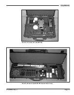
2. Check the contents of the shipping containers against the included invoice
to make sure that all components have been shipped.
3. Inspect all components for damage.
Contact CLIMAX immediately to report damaged or missing components.
NOTICE
Keep the shipping container and all packing materials for future
storage and shipping of the machine.
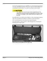
The machine ships from CLIMAX with a heavy coating of LPS 3. The recom-
mended cleaner is LPS PreSolve Orange Degreaser. All parts must be cleaned
before use.
Summary of Contents for VM1350
Page 2: ......
Page 4: ...Page B VM1350 1500 1600 Operating Manual CLIMAX GLOBAL LOCATIONS ...
Page 5: ...P N 89800 Rev 2 Page C CE DOCUMENTATION ...
Page 12: ...Page vi VM1350 1500 1600 Operating Manual This page intentionally left blank ...
Page 18: ...Page 6 VM1350 1500 1600 Operating Manual This page intentionally left blank ...
Page 44: ...Page 32 VM1350 1500 1600 Operating Manual This page intentionally left blank ...
Page 58: ...Page 46 VM1350 1500 1600 Operating Manual This page intentionally left blank ...
Page 62: ...Page 50 VM1350 1500 1600 Operating Manual FIGURE A 1 GATE VALVE GRINDING AND LAPPING MACHINE ...
Page 63: ...P N 89800 Rev 2 Page 51 ...
Page 64: ...Page 52 VM1350 1500 1600 Operating Manual ...
Page 65: ...P N 89800 Rev 2 Page 53 FIGURE A 2 440 10S N01 00 BASIC MACHINE ...
Page 66: ...Page 54 VM1350 1500 1600 Operating Manual ...
Page 67: ...P N 89800 Rev 2 Page 55 FIGURE A 3 240 11S N01 00 ELECTRIC DRIVE ...
Page 68: ...Page 56 VM1350 1500 1600 Operating Manual FIGURE A 4 240 13S N01 00 PNEUMATIC DRIVE ...
Page 69: ...P N 89800 Rev 2 Page 57 FIGURE A 5 240 15S N01 00 ELECTRIC DRIVE 115 V ...
Page 70: ...Page 58 VM1350 1500 1600 Operating Manual FIGURE A 6 440 20S N01 00 UPPER GEAR ...
Page 71: ...P N 89800 Rev 2 Page 59 FIGURE A 7 440 21S N01 00 UPPER GEAR ADDITIONAL PARTS FOR T 1000 ...
Page 73: ...P N 89800 Rev 2 Page 61 FIGURE A 9 440 33S N01 00 MACHINE ARM WITH SUBMERGING DEPTH T 800 ...
Page 75: ...P N 89800 Rev 2 Page 63 FIGURE A 11 440 35S N01 00 MACHINE ARM WITH SUBMERGING DEPTH T 1000 ...
Page 77: ...P N 89800 Rev 2 Page 65 FIGURE A 13 440 37S N01 00 MACHINE ARM GENERAL PARTS ...
Page 78: ...Page 66 VM1350 1500 1600 Operating Manual FIGURE A 14 440 40S N01 00 BALL JOINT ...
Page 79: ...P N 89800 Rev 2 Page 67 FIGURE A 15 440 41S N01 00 BALL JOINT TYPE 10 ...
Page 80: ...Page 68 VM1350 1500 1600 Operating Manual FIGURE A 16 170 30S N01 00 ...
Page 81: ...P N 89800 Rev 2 Page 69 FIGURE A 17 440 42S N01 00 BALL JOINT TYPE 15 ...
Page 82: ...Page 70 VM1350 1500 1600 Operating Manual FIGURE A 18 170 10S N01 00 ...
Page 83: ...P N 89800 Rev 2 Page 71 FIGURE A 19 MOUNTING SYSTEM ...
Page 84: ...Page 72 VM1350 1500 1600 Operating Manual FIGURE A 20 440 51S N01 00 TILTING ADAPTER ...
Page 85: ...P N 89800 Rev 2 Page 73 FIGURE A 21 440 52S N01 00 MOUNTING FOR VALVE BODIES WITH FLANGES ...
Page 86: ...Page 74 VM1350 1500 1600 Operating Manual ...
Page 87: ...P N 89800 Rev 2 Page 75 FIGURE A 22 440 53S N01 00 MOUNTING FOR VALVE BODIES WITHOUT FLANGES ...
Page 88: ...Page 76 VM1350 1500 1600 Operating Manual FIGURE A 23 440 55S N01 00 SWING CHECK ADAPTER ...
Page 90: ...Page 78 VM1350 1500 1600 Operating Manual Tooling ...
Page 91: ...P N 89800 Rev 2 Page 79 ...
Page 94: ...Page 82 VM1350 1500 1600 Operating Manual FIGURE A 27 110 20S N01 02 PLANET ARMS ...
Page 96: ...Page 84 VM1350 1500 1600 Operating Manual This page intentionally left blank ...
Page 97: ......
Page 98: ......


