P/N 89800, Rev. 2
Page A
©2017 CLIMAX or its subsidiaries.
All rights reserved.
Except as expressly provided herein, no part of this manual may be reproduced, copied, transmitted, dissem-
inated, downloaded, or stored in any storage medium, without the express prior written consent of CLIMAX.
CLIMAX hereby grants permission to download a single copy of this manual and of any revision hereto onto
an electronic storage medium to be viewed and to print one copy of this manual or any revision hereto, pro-
vided that such electronic or printed copy of this manual or revision must contain the complete text of this
copyright notice and provided further that any unauthorized commercial distribution of this manual or any
revision hereto is prohibited.
At CLIMAX, we value your opinion.
For comments or questions about this manual or other CLIMAX documentation, please e-mail
.
For comments or questions about CLIMAX products or services, please call CLIMAX or e-mail
. For quick and accurate service, please provide your representative with the following:
•
Your name
•
Shipping address
•
Telephone number
•
Machine model
•
Serial number (if applicable)
•
Date of purchase
CLIMAX World Headquarters
2712 East 2nd Street
Newberg, Oregon 97132 USA
Telephone (worldwide): +1-503-538-2815
Toll-free (North America): 1-800-333-8311
Fax: 503-538-7600
H&S Tool World Headquarters
715 Weber Dr.
Wadsworth, OH 44281 USA
Telephone: +1-330-336-4550
Fax: 1-330-336-9159
hstool.com
CLIMAX | H&S Tool (UK Headquarters)
Unit 7 Castlehill Industrial Estate
Bredbury Industrial Park
Horsfield Way
Stockport SK6 2SU, UK
Telephone: +44 (0) 161-406-1720
CLIMAX | H&S Tool (European Headquarters)
Am Langen Graben 8
52353 Düren, Germany
Telephone: +49 (0) 242-191-7712
E-mail:
CLIMAX | H&S Tool (Asia Pacific Head-
quarters)
316 Tanglin Road #02-01
Singapore 247978
Telephone: +65-9647-2289
Fax: +65-6801-0699
CLIMAX | H&S Tool (Middle East Headquarters)
Warehouse #5, Plot: 369 272
Um Sequim Road
Al Quoz 4
PO Box 414 084
Dubai, UAE
Telephone: +971-04-321-0328
Summary of Contents for VM1350
Page 2: ......
Page 4: ...Page B VM1350 1500 1600 Operating Manual CLIMAX GLOBAL LOCATIONS ...
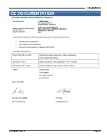
Page 5: ...P N 89800 Rev 2 Page C CE DOCUMENTATION ...
Page 12: ...Page vi VM1350 1500 1600 Operating Manual This page intentionally left blank ...
Page 18: ...Page 6 VM1350 1500 1600 Operating Manual This page intentionally left blank ...
Page 44: ...Page 32 VM1350 1500 1600 Operating Manual This page intentionally left blank ...
Page 58: ...Page 46 VM1350 1500 1600 Operating Manual This page intentionally left blank ...
Page 62: ...Page 50 VM1350 1500 1600 Operating Manual FIGURE A 1 GATE VALVE GRINDING AND LAPPING MACHINE ...
Page 63: ...P N 89800 Rev 2 Page 51 ...
Page 64: ...Page 52 VM1350 1500 1600 Operating Manual ...
Page 65: ...P N 89800 Rev 2 Page 53 FIGURE A 2 440 10S N01 00 BASIC MACHINE ...
Page 66: ...Page 54 VM1350 1500 1600 Operating Manual ...
Page 67: ...P N 89800 Rev 2 Page 55 FIGURE A 3 240 11S N01 00 ELECTRIC DRIVE ...
Page 68: ...Page 56 VM1350 1500 1600 Operating Manual FIGURE A 4 240 13S N01 00 PNEUMATIC DRIVE ...
Page 69: ...P N 89800 Rev 2 Page 57 FIGURE A 5 240 15S N01 00 ELECTRIC DRIVE 115 V ...
Page 70: ...Page 58 VM1350 1500 1600 Operating Manual FIGURE A 6 440 20S N01 00 UPPER GEAR ...
Page 71: ...P N 89800 Rev 2 Page 59 FIGURE A 7 440 21S N01 00 UPPER GEAR ADDITIONAL PARTS FOR T 1000 ...
Page 73: ...P N 89800 Rev 2 Page 61 FIGURE A 9 440 33S N01 00 MACHINE ARM WITH SUBMERGING DEPTH T 800 ...
Page 75: ...P N 89800 Rev 2 Page 63 FIGURE A 11 440 35S N01 00 MACHINE ARM WITH SUBMERGING DEPTH T 1000 ...
Page 77: ...P N 89800 Rev 2 Page 65 FIGURE A 13 440 37S N01 00 MACHINE ARM GENERAL PARTS ...
Page 78: ...Page 66 VM1350 1500 1600 Operating Manual FIGURE A 14 440 40S N01 00 BALL JOINT ...
Page 79: ...P N 89800 Rev 2 Page 67 FIGURE A 15 440 41S N01 00 BALL JOINT TYPE 10 ...
Page 80: ...Page 68 VM1350 1500 1600 Operating Manual FIGURE A 16 170 30S N01 00 ...
Page 81: ...P N 89800 Rev 2 Page 69 FIGURE A 17 440 42S N01 00 BALL JOINT TYPE 15 ...
Page 82: ...Page 70 VM1350 1500 1600 Operating Manual FIGURE A 18 170 10S N01 00 ...
Page 83: ...P N 89800 Rev 2 Page 71 FIGURE A 19 MOUNTING SYSTEM ...
Page 84: ...Page 72 VM1350 1500 1600 Operating Manual FIGURE A 20 440 51S N01 00 TILTING ADAPTER ...
Page 85: ...P N 89800 Rev 2 Page 73 FIGURE A 21 440 52S N01 00 MOUNTING FOR VALVE BODIES WITH FLANGES ...
Page 86: ...Page 74 VM1350 1500 1600 Operating Manual ...
Page 87: ...P N 89800 Rev 2 Page 75 FIGURE A 22 440 53S N01 00 MOUNTING FOR VALVE BODIES WITHOUT FLANGES ...
Page 88: ...Page 76 VM1350 1500 1600 Operating Manual FIGURE A 23 440 55S N01 00 SWING CHECK ADAPTER ...
Page 90: ...Page 78 VM1350 1500 1600 Operating Manual Tooling ...
Page 91: ...P N 89800 Rev 2 Page 79 ...
Page 94: ...Page 82 VM1350 1500 1600 Operating Manual FIGURE A 27 110 20S N01 02 PLANET ARMS ...
Page 96: ...Page 84 VM1350 1500 1600 Operating Manual This page intentionally left blank ...
Page 97: ......
Page 98: ......


