Page 30
VM1350-1500-1600 Operating Manual
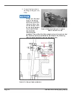
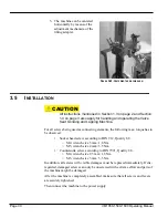
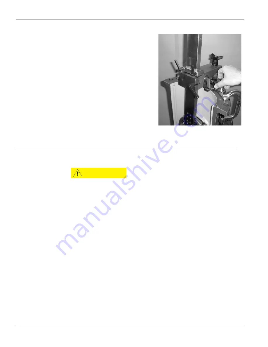
5. The machine can be centered
horizontally by means of the
adjustment mechanism of the
tilting adapter.
3.5
I
NSTALLATION
CAUTION
All instructions mentioned in Section 1.3 on page 2 and Section
1.4 on page 3 also apply for handling and operating the Valve
Seat Grinding and Lapping Machine.
For all screws being used as connecting elements, the following max. torque has to
be observed:
•
Socket head screw according to DIN 912, Quality 8.8:
○
M4, wrench size 3 mm: 1,8 Nm
○
M5, wrench size 4 mm: 3,5 Nm
•
Countersunk screw according to DIN 7991, Quality 8.8:
○
M4, wrench size 2,5 mm: 1,8 Nm
○
M5, wrench size 3 mm: 3,5 Nm
In addition, all screws with visible damages must be replaced immediately. If dis-
regarded, damaged screws can only be unscrewed with extreme effort and parts of
the machine might be damaged.
After the machine is completely assembled, make sure that all screws and levers
are securely tightened.
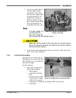
Then connect the machine to the power supply.
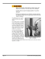
F
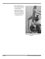
IGURE
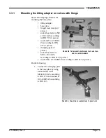
3-29. C
ENTERING THE MACHINE ARM
Summary of Contents for VM1350
Page 2: ......
Page 4: ...Page B VM1350 1500 1600 Operating Manual CLIMAX GLOBAL LOCATIONS ...
Page 5: ...P N 89800 Rev 2 Page C CE DOCUMENTATION ...
Page 12: ...Page vi VM1350 1500 1600 Operating Manual This page intentionally left blank ...
Page 18: ...Page 6 VM1350 1500 1600 Operating Manual This page intentionally left blank ...
Page 44: ...Page 32 VM1350 1500 1600 Operating Manual This page intentionally left blank ...
Page 58: ...Page 46 VM1350 1500 1600 Operating Manual This page intentionally left blank ...
Page 62: ...Page 50 VM1350 1500 1600 Operating Manual FIGURE A 1 GATE VALVE GRINDING AND LAPPING MACHINE ...
Page 63: ...P N 89800 Rev 2 Page 51 ...
Page 64: ...Page 52 VM1350 1500 1600 Operating Manual ...
Page 65: ...P N 89800 Rev 2 Page 53 FIGURE A 2 440 10S N01 00 BASIC MACHINE ...
Page 66: ...Page 54 VM1350 1500 1600 Operating Manual ...
Page 67: ...P N 89800 Rev 2 Page 55 FIGURE A 3 240 11S N01 00 ELECTRIC DRIVE ...
Page 68: ...Page 56 VM1350 1500 1600 Operating Manual FIGURE A 4 240 13S N01 00 PNEUMATIC DRIVE ...
Page 69: ...P N 89800 Rev 2 Page 57 FIGURE A 5 240 15S N01 00 ELECTRIC DRIVE 115 V ...
Page 70: ...Page 58 VM1350 1500 1600 Operating Manual FIGURE A 6 440 20S N01 00 UPPER GEAR ...
Page 71: ...P N 89800 Rev 2 Page 59 FIGURE A 7 440 21S N01 00 UPPER GEAR ADDITIONAL PARTS FOR T 1000 ...
Page 73: ...P N 89800 Rev 2 Page 61 FIGURE A 9 440 33S N01 00 MACHINE ARM WITH SUBMERGING DEPTH T 800 ...
Page 75: ...P N 89800 Rev 2 Page 63 FIGURE A 11 440 35S N01 00 MACHINE ARM WITH SUBMERGING DEPTH T 1000 ...
Page 77: ...P N 89800 Rev 2 Page 65 FIGURE A 13 440 37S N01 00 MACHINE ARM GENERAL PARTS ...
Page 78: ...Page 66 VM1350 1500 1600 Operating Manual FIGURE A 14 440 40S N01 00 BALL JOINT ...
Page 79: ...P N 89800 Rev 2 Page 67 FIGURE A 15 440 41S N01 00 BALL JOINT TYPE 10 ...
Page 80: ...Page 68 VM1350 1500 1600 Operating Manual FIGURE A 16 170 30S N01 00 ...
Page 81: ...P N 89800 Rev 2 Page 69 FIGURE A 17 440 42S N01 00 BALL JOINT TYPE 15 ...
Page 82: ...Page 70 VM1350 1500 1600 Operating Manual FIGURE A 18 170 10S N01 00 ...
Page 83: ...P N 89800 Rev 2 Page 71 FIGURE A 19 MOUNTING SYSTEM ...
Page 84: ...Page 72 VM1350 1500 1600 Operating Manual FIGURE A 20 440 51S N01 00 TILTING ADAPTER ...
Page 85: ...P N 89800 Rev 2 Page 73 FIGURE A 21 440 52S N01 00 MOUNTING FOR VALVE BODIES WITH FLANGES ...
Page 86: ...Page 74 VM1350 1500 1600 Operating Manual ...
Page 87: ...P N 89800 Rev 2 Page 75 FIGURE A 22 440 53S N01 00 MOUNTING FOR VALVE BODIES WITHOUT FLANGES ...
Page 88: ...Page 76 VM1350 1500 1600 Operating Manual FIGURE A 23 440 55S N01 00 SWING CHECK ADAPTER ...
Page 90: ...Page 78 VM1350 1500 1600 Operating Manual Tooling ...
Page 91: ...P N 89800 Rev 2 Page 79 ...
Page 94: ...Page 82 VM1350 1500 1600 Operating Manual FIGURE A 27 110 20S N01 02 PLANET ARMS ...
Page 96: ...Page 84 VM1350 1500 1600 Operating Manual This page intentionally left blank ...
Page 97: ......
Page 98: ......

