© 2003 directed electronics, inc.
35
2.
While still holding
, arm and disarm the system, then release the button.
3.
The LED will start to blink to indicate the most recent trigger and proceed down
to the eighth trigger. If fewer than eight triggers are stored in memory, the LED
will blink continuously until the system is armed/disarmed or the ignition is turned
on. For more information, please refer to the Table of Zones section of this guide.
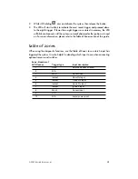
table of zones
When using the diagnostic functions, use the Table of Zones to see which input has
triggered the system. It is also helpful in deciding which input to use when connecting
optional sensors and switches.
N
NO
OTTEE:: The Warning Zone response does not report on the LED.
Zone - Number of
LED Flashes
Trigger type
Input description
1
Data
Dual Zone Shock Sensor
2
N/A
3
Mux 1
Sensor Input
4
Instant
Door Pin Input
5
Instant
Trunk Pin Input
6
Instant
Hood Pin Input
7
Instant
Ignition Input
8
Mux 2
Sensor Input
9
N/A
10
N/A
Alarm power reset


