background image

© 2003 Directed Electronics, Inc. Vista, CA  N909610 5-03

installation guide

Summary of Contents for SOLARIS 5

Page 1: ... 2003 Directed Electronics Inc Vista CA N909610 5 03 installation guide ...

Page 2: ...ion Circuitry NPC Revenger Silent Mode Soft Chirp Stinger Valet Vehicle Recovery System VRS and Warn Away are all Trademarks or Registered Trademarks of Directed Electronics Inc Vista California I IM MP PO OR RT TA AN NT T Please note that this manual was intended for US consumers and therefore includes American phrases or words ...

Page 3: ...arness wire con nection guide 22 heavy guage harness wiring dia gram 22 heavy guage harness wiring guide 22 type A positive 12 volt pulse 24 type B negative pulse 25 type C reversing polarity 26 type D after market actuators 27 type E mercedes benz and audi 1985 newer 28 type F one wire system 29 type G positive multiplex 30 type H negative multiplex 31 peripheral plug in harnesses 32 super bright...

Page 4: ...rm control technol ogy 48 smart power up II 48 remote control sensor disable 48 auto immobilization feature 49 auto immobilization sequence 49 one time valet feature 49 sensors 50 remote adjustable dual zone shock sensor 50 second unlock feature 51 troubleshooting 52 wiring reference section 53 control module connector loca tions 53 H4 connector 56 H3 connector 57 notes 59 ...

Page 5: ...HICLE ALL DOORS LEADING FROM ADJACENT LIVING AREAS TO THE ENCLOSED OR PARTIALLY ENCLOSED VEHICLE STORAGE AREA MUST AT ALL TIMES REMAIN CLOSED z Use of this product in a manner contrary to its intended mode of operation may result in property damage personal injury or death Except when performing the Safety Check outlined in this installation guide 1 Never remotely start the vehicle with the vehicl...

Page 6: ...obes computer safe test lights Test all circuits with a high quality digital multi meter before making connections z Do not disconnect the battery if the vehicle has an anti theft coded radio If equipped with an air bag avoid disconnecting the battery if possible Many airbag systems will display a diagnostic code through their warning lights after they lose power Disconnecting the battery requires...

Page 7: ...th harness z One 518C Neo Siren z One 18 pin main wiring harness z One four pin immobilizer harness z One 6 pin secondary harness z One Owner s Guide z Two window decals z Warranty registration card z Quick reference card z Presentation envelope z Intellistart 12 pin harness z Intellistart 18 pin harness z CliffNet interface cable Arm Disarm and Panic Button Silent Arm Disarm or Accessory Output B...

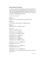
Page 8: ...sarming and panic function are controlled by this button Button The trunk release or accessory output A is controlled by this button Button Silent arm and disarm is controlled by this button Button Remote start is controlled by this button Button then Button Accessory B output is controlled by these buttons Button then Button These buttons activate SmartWindows Button then Button Accessory C outpu...

Page 9: ...ut A 200mA BLACK WHITE Dome Light Supervision Output 30 WHITE Light Flash Output WHITE Light Flash Output WHITE RED Light Flash Input BROWN Speaker Output 2 RED 12V Constant GREEN Door Trigger Input Zone 4 VIOLET Door Trigger Input Zone 4 BLUE Trunk Trigger Input Zone 5 WHITE BLUE Accessory B Output 200mA GREEN WHITE Normally Closed Input Zone 6 EMPTY Not Used GRAY Hood Trigger Input Zone 6 BROWN ...

Page 10: ...al location driver s kick panel using a factory bolt that does NOT have any vehicle component grounds attached to it A screw should only be used in conjunction with a two sided lock washer Under dash brackets and door sheet metal are not acceptable ground points It is recom mended that all security components be grounded at the same location h1 2 and h1 11 brown speaker outputs Connect the BROWN o...

Page 11: ... on zone 5 It can also be used with Directed single stage sensors h1 8 violet door trigger input zone 4 Connect the violet wire to a wire that shows 12V when any door is opened This wire will report zone 4 h1 9 green door trigger input zone 4 Most vehicles use negative door trigger circuits Connect the GREEN wire to a wire showing ground when any door is opened When connecting to newer model vehic...

Page 12: ...f the H1 12 light flash input wire Connect these to the wires in the vehicle that control the parking lights The dual outputs are designed for European vehicles with isolated parking light systems If the vehicle s parking lights are controlled by a single wire connect both WHITE wires to it h1 15 black white dome light supervision output Connect the H1 15 BLACK WHITE wire to the vehicle domelight ...

Page 13: ...k output 200mA This wire is a low current output 200mA for the horn to sound when the system has been violated h2 3 black white domelight supervision input 87 This wire determines the output of the BLACK WHITE H1 15 wire on the main 18 pin harness If the vehicle has a negative domelight circuit ground this wire if the vehi cle has a positive domelight circuit attach this wire to a 12 volt constant...

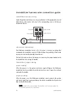
Page 14: ...ving in or removing the jumper located next to the immobilizer wires exiting the module immobilizer jumper setting jumper in setting When the jumper is in the ignition and starter signal will bypass the UltraSecure immobilizer circuitry and allow the vehicle start and run even if power has not been restored to the module jumper out setting When the jumper is out the UltraSecure immobilizer circuit...

Page 15: ...em until the intellistart installation is complete These wires are the source of current for all the circuits the IntelliStart will energize They must be connected to a high cur rent source These can be connected to the battery or the 12V power feed to the igni tion key switch the battery is preferred finding the 12V switched ignition wire The ignition wire is powered when the key is in the run or...

Page 16: ...necessary to power a cold start circuit A cold start circuit will test exactly like a starter circuit but it does not control the starter Instead the cold start circuit is used to prime the fuel injection system for starting when the vehicle is cold How to find the starter wire with your multimeter 1 Set to DCV or DC voltage 12V or 20V is fine 2 Attach the probe of the meter to chassis ground 3 Pr...

Page 17: ... 12V release the pedal and make sure it goes back to zero 5 If it does return to zero this is the correct brake wire finding the accessory heater wire An accessory heater wire will show 12V when the key is in the accessory and run positions It will not show 12V during the cranking cycle There will often be more than one accessory wire in the ignition harness The correct accessory wire will power t...

Page 18: ...r 1 Set to ACV or AC voltage 12V or 20V is fine 2 Attach the probe of the meter to chassis ground 3 Start and run the vehicle 4 Probe the wire you suspect of being the tachometer wire with the red probe of the meter 5 If this is the correct wire the meter will read between 1V and 6V and fluctuate with the RPM of the motor finding the wait to start bulb wire for diesels In diesel vehicles it is nec...

Page 19: ...until the light goes out and then reads 12 volts you have isolated the correct wire and the wire s polarity is positive H3 harness wire connection guide harness wiring diagram ___ ___ ___ ___ ___ ___ ___ ___ ___ ___ ___ ___ BLACK GRAY RPM Input BLUE WHITE Brake Light Input BLUE GREEN Shut Down BLUE YELLOW Positive Switching Wait To Start Bulb Diesel BLUE BLACK Negative Switching Wait To Start Bulb...

Page 20: ... disarm This wire will produce a 200mA output prior to a remote start sequence Connect this wire to the factory alarm disarm wire in the vehicle h3 5 red battery Positive 5 amp fuse 12V input Connect this wire to a constant 12V source h3 6 blue orange third ignition trigger This wire will trigger an additional relay for a third ignition output When needed connect this wire to an optional relay h3 ...

Page 21: ... NOT in reverse 2 When the intellistart is programmed to Manual transmission mode H3 1 black green is NOT grounded connect the H3 10 blue green wire to the park ing brake indicator wire The wire should show ground when the parking brake is set and 12V when the parking brake is NOT set h3 11 brake light input The IntelliStart monitors the brake light to prevent an unauthorized driver from driv ing ...

Page 22: ... turned off or when a door is opened h4 2 red 12V input N NO OT TE E If the factory supplies two separate 12V feeds to the ignition switch con nect one RED wire of the intellistart to each feed at the switch Remove the 30 amp fuse prior to connecting to the 12V wire and do not replace until the intellistart installation is complete This wire is the source of current for all the cir cuits the Intel...

Page 23: ... If the factory supplies two separate 12V feeds to the ignition switch con nect one RED wire of the satellite to each feed at the switch Remove the 30 amp fuse prior to connecting this wire and do not replace them until the satellite has been plugged into the control module This wire is the source of cur rent for all the circuits the relay satellite will energize It must be connected to a high cur...

Page 24: ...f wires that pulse 12 volt alter nately on lock and unlock make sure that it is not a Type C direct wire system Cut the wire that pulses 12 volt on lock and then operate the switch to unlock z If all doors unlock the vehicle uses type A system z If you lose all door lock operation in both directions you are operating the mas ter switch in a Type C system z If you lose all door lock operation of on...

Page 25: ...lse locking are high current so a 451M or 2 relays need to be used The switch will have three wires on it and one wire will test ground all the time One wire will pulse negative when the switch locks the doors and the other wire will pulse negative when the switch unlocks the doors This type of system is difficult to mistake for any other type I IM MP PO OR RT TA AN NT T Remember that these wires ...

Page 26: ...ires The switch that lost all operation is the master switch If one switch works in both directions and the other switch works in only one direction you have a Type A system If both switches still operate but one or more doors has stopped responding entirely you have cut a motor lead Reconnect it and continue to test for another wire Once both wires have been located and the master switch has been...

Page 27: ...red Vehicles without factory power door locks require the installation of one actuator per door This requires mounting the door lock actua tor inside the door Other vehicles may only require one actuator installed in the dri ver s door if all door locks are operated when the driver s lock is used The fuse used on 12 volt inputs should be 7 5A per motor installed in the vehicle ...

Page 28: ...s from the passenger key cylinder If all the doors lock the vehicle s door lock system can be controlled with just two relays optional The control wire can be found in either kick panel and will show 12 volt when doors are unlocked and ground when doors are locked To interface see diagram below The system must be programmed for 3 5 second door lock pulses up to 1993 and 1 second pulse 1994 or newe...

Page 29: ...d cutting the wire to lock the door In some vehicles these functions are reversed Type F door locks are found in late model Nissan Sentras some Nissan 240SX and Nissan 300ZX 1992 up They are also found in some Mazda MPVs some Mitsubishis and Lotus One relay optional is used to interface to this type of system as follows ...

Page 30: ...o relays or a DEI 451M must be used Single Resistor Type If one resistor is used in the door lock switch key cylinder the wire will pulse 12 volt in one direction and less than 12 volt when operated in the opposite direction Two Resistor Type If two resistors are used in the factory door lock switch key cylinder the switch key cylinder will read less than 12 volt in both directions ...

Page 31: ...d Single Resistor Type If one resistor is used in the door lock switch key cylinder the wire will pulse ground in one direction and resistance to ground when operated in the opposite direction Two Resistor Type If two resistors are used in the factory door lock switch key cylinder the door lock switch key cylinder will read resistance to ground in both directions 2003 directed electronics inc 31 ...

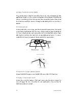
Page 32: ...e LED with a bezel the LED fits into a 5 16 inch mounting hole If flush mounting the LED from the back of a panel drill a mounting hole using a 17 64 inch drill bit Be sure to check for clearance prior to drilling the mounting hole plain view 2 valet The Valet Program switch should be accessible from the driver s seat It plugs into the blue port on the side of the unit Consider how the switch will...

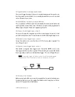
Page 33: ...d or under the dashboard away from metal but range will be reduced Metallic window tint can also affect range so this should be a consideration when determining the mounting location After determining the best mounting location follow these steps 1 Clean the mounting area with a quality glass cleaner or alcohol to remove any dirt or residue 2 Plug the receiver antenna cable into the receiver anten...

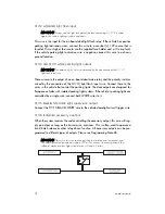
Page 34: ...en silencing While the siren is sounding press the arm disarm button once to silence the siren but leave the system in the armed state To disarm the system press the arm disarm but ton a second time N NO OT TE E If the remote control battery is low the siren will generate a single low pitched chirp when disarming multiple event total recall This will report the last eight system triggers 1 Press a...

Page 35: ... to the Table of Zones section of this guide table of zones When using the diagnostic functions use the Table of Zones to see which input has triggered the system It is also helpful in deciding which input to use when connecting optional sensors and switches N NO OT TE E The Warning Zone response does not report on the LED Zone Number of LED Flashes Trigger type Input description 1 Data Dual Zone ...

Page 36: ...ng with a mouse This eliminates the need for programming grids and lengthy programming sequences For a complete guide to system programming using the Cliffnet Wizard Pro refer to the Cliffnet Wizard help menu manual programming instructions Be sure to document changes by taking note of all feature changes made in program ming mode To enter the User Selectable Features programming 1 Ignition on Tur...

Page 37: ...eature in the same column press the same number of times as the desired feature within 60 seconds to change a feature in a different column begin at step 4 by entering the column number first and then the row number N NO OT TE E Refer to the Feature Descriptions sections of this guide for important notes and descriptions of the system features and programming 7 Exit programming To exit programming...

Page 38: ... z Auto learn new remote controls to the system in the standard button configu ration For more information see programming note 1 auto passive arm on off z On When the system sees the ignition turn off and the last protected entry door hood or trunk close it will begin a 30 second countdown before arming itself After the first five seconds you will hear two chirps and the lights will flash The sys...

Page 39: ... off z Off The doors will not automatically unlock when the ignition is turned off auto passive arm lock on off z On The doors will lock when the system passively arms This feature only applies when passive arming is programmed on z Off The doors will not lock when the system passively arms siren duration 30 60 90 z The system will sound the alarm for the programmed duration 30 60 90 seconds durin...

Page 40: ...m the system via the PlainView 2 Valet switch z Off There is no entry delay when the system has passively armed The system will trigger instantly when a door is opened reset to default settings z All system settings except PIN and remote programming in the User Programming grid will be reset to their default factory setting as indicated in bold lettering z Press the arm disarm button of the TX the...

Page 41: ...gramming the remaining channels accessory a output z The transmitter channel programmed into this feature will activate the accessory output accessory b output z The transmitter channel programmed into this feature will activate the accessory output silent mode z The transmitter channel programmed into this feature will arm disarm the system but the siren will not chirp remote valet z The transmit...

Page 42: ...cribed below to enter the Installer Selectable Features grid Hold Chirp Release After entering the PIN code press and hold until the siren chirps once Continue holding for approximately 10 seconds until the siren chirps three times then release the button You have now entered the feature selection posi tion of the Installer Selectable Features grid P1 Pulsed channel output is disabled with the ign...

Page 43: ...nds in length delay domelight z On Smart auto testing will ignore the domelight until it goes off z Off Smart auto testing will generate a warning to indicate the door is open accessory output b auto activation N NO OT TE E The accessory output will not auto activate if programmed to latched setting z Off z Arm The accessory output will auto activate when the system is armed z Disarm The accessory...

Page 44: ...d by button s controlling accessory if on will turn off when the ignition is turned on one time valet on off z On Allows one time valet mode feature z Off Does not allow one time valet mode feature accessory output a timer duration z Start Timer Press the arm disarm button the siren will chirp to signal the start of the timer duration setting z Stop Timer Press the arm disarm button the siren will...

Page 45: ...ies only if SmartWindows is installed z Enter this feature and then follow the programming instructions included with SmartWindows horn output pulsed latched z Pulsed H2 9 YELLOW WHITE wire will generate a pulsing output when the alarm is in full trigger When arming and disarming the output does not operate z Latched H2 9 YELLOW WHITE wire will generate a constant output when the alarm is in full ...

Page 46: ...er entering this feature press the arm disarm button The siren will generate a five second sample of each available siren sound Perform the following steps to add or delete that specific sound z Add sound Press on the PlainView 2 Valet switch while playing the desired sound to add that sound z Delete sound Press on the PlainView 2 Valet switch while playing the desired sound to delete that sound N...

Page 47: ... 4 Wait for two siren chirps after a five second pause or five seconds after the last digit has been entered if using less than four digit code number 5 Turn off the ignition the siren will chirp three times 6 The programming mode is now exited z PIN Code Confirmation Procedure Begin this procedure within 15 seconds of finishing the programming sequence or the new code will not be set 1 Turn on th...

Page 48: ...test the system once you have it installed Resetting FACT II requires the 60 minute time period expiring without attempted triggers or the ignition to be turned on and off This allows the system to be repeatedly triggered disarmed and rearmed and still allow FACT II to bypass a faulty zone N NO OT TE E Remember to reset with the ignition when testing sensors smart power up II The Smart Power Up II...

Page 49: ...mmobilization circuits activate and engage the starter and ignition interrupt 3 LED blinks at normal speeds Disarm the system when immobilized Use one of the following methods to turn off auto immobilization z Turn ignition on and press the arm disarm button of the transmitter z Arm the alarm and then disarm the alarm z Turn the ignition on and enter the system valet PIN code one time valet featur...

Page 50: ...LY strike the pillars using the heel of your hand it is more than sufficient for the sensor to distinguish this as a theft attempt N NO OT TE E You MUST exit using the ARM DISARM button after programming to lock in the new settings Read the following instructions thoroughly for a full understanding of how to prop erly adjust this sensor 1 Disarm system 2 Transmit Channel 15 Press 3 times then 1 ti...

Page 51: ...Away zone setting z Siren chirps 2 times z Primary zone can now be re adjusted as described in step 3 z Or press again to lock in primary zone setting and exit pro gramming mode z The siren will chirp 3 times when sensor adjustment mode has been exited z Auto Scroll for adjusting sensitivity press and hold or to increase or decrease sensitivity setting several lev els rapidly second unlock feature...

Page 52: ...ong door input has been used The system will not passively arm until it is remotely armed and then disarmed z Are the door inputs connected Is a BLUE wire connected to the door trigger wire in the vehicle The GREEN H1 9 or the VIOLET H1 8 should be used instead The PlainView 2 Valet switch does not work z Is the quick disconnect plugged in correctly z Is it plugged into the correct socket z Check ...

Page 53: ... 2003 directed electronics inc 53 wiring reference section control module connector locations intel H1 6 pin Harness H2 ...

Page 54: ...www directed com 54 H1 connector H2 connector EMPTY ...

Page 55: ... 2003 directed electronics inc 55 intellistart module connector location CLIFFORD intellistart CliffNet Wizard port CliffNet Wizard port H3 H4 ...

Page 56: ...itch IGN key side IGN ignition side STR key side STR starter side Immobilizer Harness Connector Orange Accessory Green Blue Coil side ignition White Blue Starter side starter Gray heater a c Gray Orange heater 2 Orange Gray ignition 2 H4 Connector To System Module To Intellistart Control unit 30 amp Fuse 30 amp Fuse Red battery Red battery To battery ...

Page 57: ... 2003 directed electronics inc 57 H3 connector ...

Page 58: ...www directed com 58 ...

Page 59: ...__________________ ________________________________________ ________________________________________ ________________________________________ ________________________________________ ________________________________________ ________________________________________ ________________________________________ ________________________________________ ________________________________________ ____________...

Reviews: