RADIUS SL PLUS 03.2019 en
18
6.2.3.1 Adjustment without hydraulic pressure to the unit
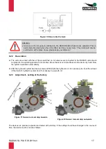
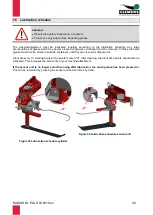
a) Sensor rod end stop inwards (Figure 11):
The purpose of this setting is to prevent the valve piston from being pressed in too deeply, thereby damaging
the valve bottom.
Loosen the counternut (item 1) and turn the screw (item 2) with its head towards the support (item 3); if you
now press the sensor rod unit inwards, the end stop (item 4) must not touch the screw head (item 2). Hold the
sensor rod unit pressed in firmly and turn the screw (item 2) in the direction of the end stop (item 4). When the
head of the screw (item 2) touches the end stop (item 4), turn it another half turn. This ensures that the piston
of the valve does not touch the valve bottom. Tighten the counternut (item 1).
b) Sensor rod end stop outwards (Figure 12):
This setting is used to position the sensor unit so that the pressure section (item 5) just comes into contact
with the valve piston (item 6) in the rest position of the device. Loosen the counternut (item 7)
and turn the
screw (item 8) inwards so that there is play between item 5 and item 6. Check whether the valve piston (item
6) is smooth-running and fully extended. Now turn the screw (item 8) back so that the play between item 5 and
item 5 is just eliminated. Tighten the counternut (item 7).
6.2.3.2 Adjustment with hydraulic pressure to the unit (stroke limitation)
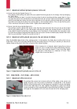
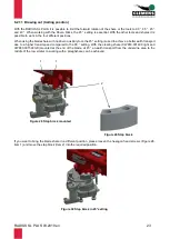
Move the RADIUS blade share to the working position. In this position, the blade share must be able to move
forward by 5 mm (1/5”) if you press forward from the rear at the outer end. This play is necessary to keep some
distance between the piston rod of the cylinder and the cylinder bushing.
If this clearance is not present, adjust it using the set screw
(Figure 13, item 1) located in the stop of the bearing housing.
First loosen the counternut (Figure 13, item 2) and then adjust
the setscrew so that there is a clearance of 5 mm. Then
retighten the counternut (item 2).
6.2.4 Adjustments
– tool change – add-on tools
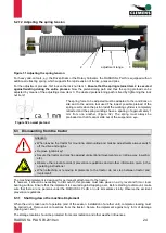
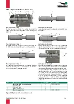
6.2.4.1 Adjustment of the sensor rod
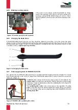
The setting of the sensor rod is simple and fast: Lift the button on the sensor unit
slightly and then move the sensor rod forwards or backwards in the desired
direction. When driving uphill, it is advantageous to position the sensor rod slightly
in front of the blade share. The same applies if the plants have grown at an angle
(inclined forwards) or if the forward speed is higher than 8 km/h (5mph). The sensor
rod height can be adjusted via the screw and counternut on the clamping piece.
Figure 13 Adjustment with hydraulic pressure to the unit
1
2
Figure 14 Adjustment of the sensor rod


