CleaverBrooks Hawk 1000 Operation Manual Download Page 24

Section 3 — Hardware Checkout

Hawk 1000

3-6

Part No. 750-366

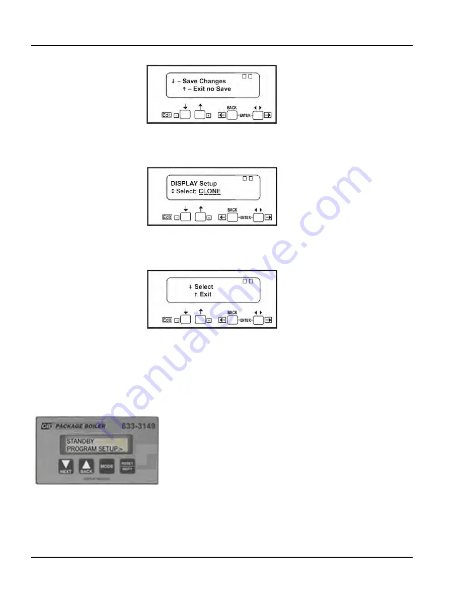
Press down arrow key to save changes.

Press ENTER buttons at the same time.

Press upper arrow key to exit.

3.1.5  Burner Control Modbus Address and Baud Rate - CB120E

The CB120E has built-in Modbus capability; for proper communications the ModBus baud rate and node 
address need to be correctly set. To check the settings, the CB120E must be powered.

Press the <BACK> or <NEXT> key on the CB120E display until the screen displays PROGRAM SETUP>.

Summary of Contents for Hawk 1000

Page 1: ...750 366 07 2013 Hawk 1000 Boiler Control Operation Manual...

Page 2: ...m of certain repetitive chores and give him more time to devote to the proper upkeep of equipment It is solely the operator s responsibility to properly operate and maintain the equipment No amount of...

Page 3: ...Cleaver Brooks HAWK 1000 Boiler Control Operation Manual Manual Part No 750 366 07 2013 Please direct purchase orders for replacement manuals to your local Cleaver Brooks authorized representative...

Page 4: ......

Page 5: ...stem Configuration Introduction 4 2 Main Menu 4 2 Boiler Overview 4 3 System Configuration 4 4 Section 5 Commissioning Commissioning the Actuators 5 2 Setting Combustion Parallel Positioning 5 4 Setti...

Page 6: ......

Page 7: ...eaverbrooks com Section 1 General Introduction 1 2 System Description 1 3 Hawk 1000 System Features 1 4 Safety Provisions and Diagnostics 1 5 Burner Management 1 5 Boiler Controls 1 5 Inputs and Outpu...

Page 8: ...able Boiler Controller and Burner Management Controller as well as other boiler operating and ancillary controls The HAWK 1000 system incorporates a user friendly graphical Human Machine Interface HMI...

Page 9: ...ding Plant Automation Systems via an optional CB PT protocol translator EtherNet Internet communication also enables remote monitoring of the Hawk 1000 Boiler Control System Additional software and or...

Page 10: ...r Level Master water level interface Available input for any ONE of the following water temp Steam Return Temp or Outdoor reset hot water boilers Remote Modulation by communications EtherNet Remote Se...

Page 11: ...Operating and Modulating Controls Monitors Low Water Cut Off Monitors Burner Control alarm terminal Non Recycle Limit Relay de energizes on PLC system errors or faults Transmitter input signal out of...

Page 12: ...sure I1 5 1 I5 5 Ready To Start Limits Closed 1 O6 5 Prove High Fire Open High Fire Oil Valve 2 1 Oil Drawer Switch I1 6 1 I5 6 Ext Device Start Interlock FAD 1 O6 6 Alarm Bell 1 Atomizing Air Pressur...

Page 13: ...erbrooks com Section 2 System Components Overview 2 2 Base Unit 2 2 Human Machine Interface HMI 2 3 Communications 2 4 Modbus 2 4 Ethernet 2 5 USB 2 5 Sensor Inputs 2 6 Steam Systems 2 6 Hot Water sys...

Page 14: ...Brooks firetube and watertube boilers yet allows easy configuration for specific boiler applications The Boiler Controller program logic is password secured ensuring tamper proof controller operation...

Page 15: ...boiler parameters at a glance and provides easy menu navigation for configuring system parameters setting of combustion monitoring the boiler processes and managing and annunciating system alarms The...

Page 16: ...are managed by the SM2 module located to the right of the base unit in slot 4 HAWK 1000 devices that communicate using Modbus include the burner flame safety control and the fuel air and FGR actuator...

Page 17: ...SB communications are used to connect a laptop computer for diagnostic purposes Figure 2 4 L24ER Communication Ports Ethernet ports bottom of Base Unit PORT 1 PORT 2 0 1 2 3 4 5 6 7 8 9 10 11 12 13 14...

Page 18: ...cation for the thermowell is a 1 2 NPT coupling at the right hand side center line of the boiler shell If this location is not available an unused feedwater connection may be used Water Level sensor i...

Page 19: ...nel and Field Wiring Terminations 3 3 SM2 Module DIP Switch 3 3 Burner Control Modbus Address and Baud Rate CB780E 3 4 Burner Control Modbus Address and Baud Rate CB120E 3 6 PLC Switch 3 7 Modbus Actu...

Page 20: ...also be connected to the boiler controller 3 1 1 DIN Rail Latch and Expansion I O Module Locking Levers Before powering up the control system for the first time check that all the DIN rail latches an...

Page 21: ...e tight and that field wiring terminations are completed and secure 3 1 3 SM2 Module DIP Switch Verify that the SM2 Module DIP switch setting is as shown below the top switch is to the left the bottom...

Page 22: ...s are made using the 780E keypad display Press the left three buttons of the keypad display module for one second then release DISPLAY Setup will appear Press the two ENTER buttons at the same time Pr...

Page 23: ...rt No 750 366 3 5 Press down arrow key to save changes Press down arrow key until MB BAUD is displayed Press ENTER buttons at the same time Press down arrow to select Using up or down arrow key select...

Page 24: ...arrow key to exit 3 1 5 Burner Control Modbus Address and Baud Rate CB120E The CB120E has built in Modbus capability for proper communications the ModBus baud rate and node address need to be correctl...

Page 25: ...of the actuator Be sure that the mounting surface rests flat against the mounting bracket and is secure The actuator output drive shaft should be connected to the valve shaft with a suitable coupling...

Page 26: ...Section 3 Hardware Checkout Hawk 1000 3 8 Part No 750 366 Figure 3 5 SM2 wiring to actuators Figure 3 6 Actuator daisy chain w plug connections MODBUS ACTUATORS PLUG WIRED FUEL 1 ACT 1 FUEL 2 ACT 1...

Page 27: ...3 Setting The Modbus Node Address The actuators are required to have unique Modbus node addresses The node address is set using a rotary style switch located on the actuator front plate Turn to the de...

Page 28: ...ower present but no commands received from PLC ON Solid is the normal state for an actuator not required by the PLC at the time such as the Fuel 2 Actuator when the Fuel Selector is in the Fuel 1 posi...

Page 29: ...en the main fuel valve is closed Moving the actuators manually while the main fuel valve is open will generate a fault Releasing the manual pushbutton will allow the PLC to automatically command the a...

Page 30: ...Section 3 Hardware Checkout Hawk 1000 3 12 Part No 750 366...

Page 31: ...enu 4 2 Boiler Overview 4 3 System Configuration 4 4 Boiler Type and Media 4 6 Fuel Configuration 4 11 Flame Safeguard 4 12 Analog Inputs 4 13 Remote Modulation Remote Set Point 4 15 Actuator Selectio...

Page 32: ...ree levels of security Operator Service and Factory Pressing a gray pushbutton will display the login entry window 4 2 Main Menu The Main Menu Figure 4 2 is the first screen to appear when power is ap...

Page 33: ...4 3 Main Menu initial startup 4 3 Boiler Overview The Boiler Overview display Figure 4 4 serves as the main point of interface for the operator The primary purpose of the display is to monitor the cur...

Page 34: ...st step in commissioning t h e b o i l e r is to configure the control system options On the Main Screen press System Config A warning message is displayed Press System Config again a final warning sc...

Page 35: ...rt to Pilot Signal Select CB120E Only Analog Input I 2 2 Analog Input I 2 3 Remote Modulation Setpoint Signal Selection Dual Setpoint Selection Actuator Selection VFD Option Selection requires additio...

Page 36: ...st step in the configuration procedure is to select the boiler media and type Any time a gray button appears a user I D and password are required for user input Pressing Boiler Media or Boiler Type wi...

Page 37: ...word will bring up an alphanumeric keypad Use this or the HMI hardware keypad to enter your user name and password A USB keyboard may also be used Type the password user name followed by the Enter key...

Page 38: ...y valve setpoint and NOx level To change the default values press the desired button and a keypad will appear allowing user input Selecting boiler type and media will also bring up the Next button all...

Page 39: ...ed value and press the Enter key If the entry is valid the value will be accepted and the keypad will disappear Note that all entries can be made by touching the HMI screen or by using the HMI keypad...

Page 40: ...itter is not scalable The transmitters used must be rated to accommodate the required range If the Max Rated Temperature 250 Deg F the Supply Temp Transmitter is set to 50 300 Deg F If the Max Rated T...

Page 41: ...e for each fuel for this specific job When pressing the Fuel Type push button a selector is displayed The up down arrows can be used to select the correct fuel Press the enter key to accept the select...

Page 42: ...type of Flame Safeguard used for the specific job The CB780E and CB120E are the two selections available on the Hawk 1000 If CB120E is selected the Revert to Pilot Option is available not available o...

Page 43: ...I 2 2 is Water Temperature For Hot Water systems Analog Input I 2 2 can be selected as None Outdoor Temperature or Return Temperature Caution Revert to Pilot modes are to be determined in the field a...

Page 44: ...ected it is mandatory that the Level Master is the sensor used to measure the water level Remote Set Point is not available on Low Emission boilers 60ppm 750 281 Level Master For Hot Water systems Ana...

Page 45: ...Fire and 20ma High Fire Remote Modulation by Analog Input Signal Selection The user can select between HMI or digital input to enable Remote Modulation Select Digital In if another control system wil...

Page 46: ...arm and Limits Screen by setting the Remote Setpoint Scaling values zero and span of the remote 4 20mA signal Remote Set Point by Analog Input Signal Selection The user can select between HMI or digit...

Page 47: ...al Set Point control This option is not allowed for low emission steam boilers 60 ppm 4 4 6 Actuator Selection FGR Actuator The FGR actuator should be selected as Yes if it is present on this system T...

Page 48: ...ilable options are None PowerFlex and Other Mfg Selecting PowerFlex assumes you are using either the PowerFlex 400 PowerFlex 70 Enhanced or PowerFlex 700 Vector drive All drives types use 4 20mA comma...

Page 49: ...s the speed of the combustion air fan motor for the purposes of improving boiler efficiency and reducing electrical energy consumption 4 4 8 Options Oxygen Analyzer The Oxygen O2 Analyzer See Figure 2...

Page 50: ...guration screen between Yes and No If enabled the Low O2 Shutdown Setpoint and Low O2 shutdown time delay can be adjusted on the alarms and limits screen Hot Standby The Hot Standby function maintains...

Page 51: ...re is displayed on the boiler overview screen Figure 4 21 Options When Outdoor Reset is selected the outdoor temperature and water temperature setpoints should be entered from the Setpoints screen See...

Page 52: ...number must be entered again in order for this information to appear on the Master Panel HMI Auxiliary Alarm 1 3 If the system has auxiliary alarms the text that is displayed when the alarm is trigge...

Page 53: ...le if this is a new system configuration or a system configuration parameter marked with an asterisk has been changed Figure 4 24 Configuration summary To complete system configuration press the Confi...

Page 54: ...Section 4 System Configuration Hawk 1000 4 24 Part No 750 366...

Page 55: ...or O2 Trim 5 8 Setting Combustion Low High Low 5 8 Firing Rate Screen 5 9 Alarms and Limits 5 11 Low O2 5 11 Low Steam Pressure 5 11 Mod Rate Limiter Max O2 Correct Remote Shutdown by Comms 5 12 Stack...

Page 56: ...on Actuator for the desired actuator and read the warning screen which follows In this example we will be commissioning the air actuator Figure 5 2 Actuator commissioning NOTE Any combustion curves pr...

Page 57: ...st With the actuator fully open closed press Store Open Close Figure 5 4 Actuator stroke Note CCW rotation means the closed position will be greater than the open position CW rotation means the open p...

Page 58: ...available on the Main screen To begin the procedure press Set Combustion and observe the warning that follows Figure 5 6 Begin combustion setup Press I READ THE WARNING I AM QUALIFIED to continue An...

Page 59: ...and Lightoff positions Figure 5 7 Purge Lightoff help For a valid Purge position the air actuator must be greater than 80 open To position the actuators in setting combustion first press the button fo...

Page 60: ...the VFD purge value is automatically set at 100 5 2 2 Store Lightoff When the purge position has been set the Store Lightoff button will be available on the Combustion Setup screen After positioning t...

Page 61: ...f The Flame Safeguard will sequence through pilot trial and main flame and the burner will ignite The actuators can now be positioned for the first point 8 points minimum must be stored for a valid cu...

Page 62: ...be active Point 1 will be low fire Point 2 will be high fire 5 4 Setting Combustion Low High Low Low High Low combustion is only available with Cleaver Brooks Model 4 Model 5 boilers Low High Low is o...

Page 63: ...urrent positions until moved manually by the operator using the Control Output Decrease and Increase buttons Figure 5 15 In Automatic mode control output is based on demand the actuators will be posit...

Page 64: ...e control will revert to Local Auto mode The Adjust Gains button accesses the system PID tuning Default values are P 5 I 5 D 0 Figure 5 18 Adjust Gains Adjust Setpoint allows adjustment of Setpoint 1...

Page 65: ...ate are not rate limited 5 6 Alarms and Limits Alarms with configurable parameters and firing rate setpoint limits can be edited from this screen Configurable items include the following 5 6 1 Low O2...

Page 66: ...e setting determines what the boiler will do upon a failure of remote communications shut down or remain in its last state 5 6 4 Stack Low Temp Hold This feature is only available with FGR Selectable...

Page 67: ...Set Point 100 Valid entries for Off dP are from On dP to the calculated value where Off Point is not greater than the Safety Valve setpoint 5 7 2 Outdoor Temperature Reset Hot Water only If Outdoor R...

Page 68: ...ear on the Overview and Firing Rate screens Initiated by process variable If Initiate by process variable is selected Revert to Pilot is initiated when steam pressure is greater than or equal to Rever...

Page 69: ...rol button will appear on the Main screen Figure 5 27 O2 Trim is accomplished by means of the air actuator or by the VFD if present if VFD is in Bypass the air actuator is used A manual operating mode...

Page 70: ...onfiguration press the desired field in the Set New Ethernet Configuration area If user is logged in at the proper level a numeric keypad will appear Enter the new data and press the enter key or use...

Page 71: ...ch is used to provide a digital input to Boiler 2 PLC I 5 14 to designate Boiler 2 as the lead boiler With input energized set point 2 is selected Set point 2 is designated for the boiler operation wh...

Page 72: ...ours thermal shock protection is activated For Hot Water Boilers Thermal shock protection is activated when actual water temperature is below minimum temperature 150F for Firetube 120F for FLX Maximum...

Page 73: ...averbrooks com Section 6 Diagnostics and Troubleshooting System Monitoring and Diagnostics 6 2 Boiler Overview 6 2 Burner Control 6 2 System Information 6 3 PLC Info 6 3 Diagnostic Screens 6 4 PLC Sta...

Page 74: ...ol screen gives details on the installed Flame Safeguard CB780 or CB120 Figure 6 2 Burner Control screens The status of the Flame Safety control is shown as well as the status of the inputs that allow...

Page 75: ...nal interlock is proven Note The external interlock must be jumped if not used ALFCO Assured Low Fire Cut Off An external isolated start stop contact can be provided to shut down the boiler This conta...

Page 76: ...The controller is in Program or Test mode Green The controller is in Run mode FORCE Off No tags contain I O force values I O forces are inactive disabled Yellow I O forces are active enabled I O forc...

Page 77: ...port has an IP address but no CIP connections are established Red The port has detected that the assigned IP address is already in use Flashing red green The port is performing its power up self test...

Page 78: ...Section 6 Diagnostics and Troubleshooting Hawk 1000 6 6 Part No 750 366...

Page 79: ...se 120 Watt for 50NM Actuator 1 848 01623 000 Centre 60x30x10 No Cut outs Conversions uses a different size 1 983 00083 000 6 Amp 1 836 00620 000 Qty 1 add another if oil heater for 6 oil is required...

Page 80: ...er 1 833 02725 000 Wiring Sub Base 1 833 03495 000 Infared Amplifier 1 833 02730 000 Purge Timer Card 1 817 04133 000 Scanner IR 817 1742 880 02118 000 CB 780E w UV Scanner Kit 1 833 03517 000 CB 780E...

Page 81: ...cify Range includes Valve 1 817 09768 000 PMP51 E9K7 142 includes Isolation Valve 1 817 05167 000 E H TH13 1A13X1BBA1AK NON HART 2 5 Thermowell 50 900 Deg F 1 817 05166 000 E H TH11 B8CBBA1AK4 NON HAR...

Page 82: ...Section 7 Parts Hawk 1000 7 4 Part No 750 366...

Reviews: