


Model FLE Assembly
Casing Assembly
750-192
3-19
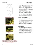
Figure 3-42. Insulation in the Gaps
Figure 3-43. 1-1/2" blanket insulation on refractory
tile with square piece
Figure 3-44. Top view of the three different pieces of
blanket insulation
12. Install Insulation Under Tubes
•
Install pyro-log insulation blocks (872-911) in the
pass openings near the rear and in the gap left by the
tubes at the bottom (Figure 3-42). The insulation
blocks should be compressed together slightly and
should be installed flush with the outside of the
tubes. They should be turned vertically to fill in the
turn around area. Trim to fit as necessary.
•
Install 1-1/2" blanket insulation (872-279) below the
boiler tubes, on top of the refractory running the full
length of the boiler (Figure 3-43 and 44). Boilers
sizes 150 through 350 do not get this strip of insula-
tion.
•
Install a 12" x 12" piece (14” by 14” for 800-1000)
of 1-1/2" blanket insulation at the rear of the boiler in
the refractory on both sides. Use a spray adhesive to
hold the insulation in place (Figure 3-43).
•
Install 1-1/2" blanket insulation in front of the first 1-
1/2” strip of insulation and on the refractory from the
front wall to the 12" x 12" piece of insulation at the
rear of boiler (Figure 3-44).
13. Install Pass Insulation
•
Spray adhesive (94-475) on the tubes above and
below the pass opening. Install 1-1/2" blanket insula-
tion onto the entire side of the tubes and pyro-log,
pressing it onto the adhesive. Trim any excess blan-
ket at the end.
Note:
As with all insulation, the pyro-log should
be tight to the next piece and to the refractory
bricks with no gaps.
Note:
the blue rigidizer faces inside.
Figure 3-45. Insulation along Pass Opening
Do not leave gaps when installing insulation.
Always ensure a secure fit between the insula-
tion and any attaching or abutting surfaces, as
well as between adjacent pieces of insulation.
Failure to observe this precaution may result in
equipment failure or unsafe operation.
!
DANGER
WARNING
Summary of Contents for FLE
Page 1: ...Model FLE Assembly Instructions 750 192 07 09 Field Erectable Flexible Watertube Boiler ...
Page 4: ...iv Notes ...
Page 8: ...viii ...
Page 16: ...General Description Model FLE Assembly 1 8 750 192 ...
Page 34: ...3 2 750 192 Figure 3 1 Typical Hot Water Flextube Casing ...
Page 36: ...3 4 750 192 Figure 3 2 Typical Low Pressure Steam Flextube Casing ...
Page 38: ...3 6 750 192 Figure 3 3 Typical High Pressure Steam Flextube Casing ...
Page 56: ...Casing Assembly Model FLE Assembly 3 24 750 192 ...
Page 58: ...750 192 4 2 Figure 4 2 Fuel Train Components ...
Page 60: ...4 4 750 192 Figure 4 5 Typical conduit layout ProFire burner on a hot water Flextube boiler ...
Page 61: ...750 192 4 5 Figure 4 6 Typical conduit layout ProFire burner on a steam Flextube boiler ...
Page 62: ...4 6 750 192 Figure 4 7 Nameplate locations hot water boiler ...
Page 63: ...750 192 4 7 Figure 4 8 Nameplate locations steam boiler ...
Page 64: ...e mail info cleaverbrooks com Web Address http www cleaverbrooks com ...


