


Casing Assembly
Model FLE Assembly
3-14
750-192
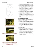
Figure 3-24. Finishing the Wetpack Insulation
Installation
Figure 3-25. Packing the Top of the Walls
Figure 3-26. Filling the Joint with Silicone Caulking
5. Finishing the Wetpack Installation
Around the Lower Drum
•
Unfold the wetpack to cover the lower drum and
tubes. Cover the entire base drum, overlapping
adjoining wetpack rolls. Continue to mold the wet-
pack around the lower drum and tube sections to
prevent the plates from coming apart while packing
the insulation (Figure 3-24).
•
The wetpack should be positioned to be level with, or
just outside the base refractory at the front.
6. Finish Installing Backing Plates
•
As in step 3, install the front upper and lower back-
ing plates.
7. Install Front Wall Section
To install the front wall section, repeat the same
steps used to install the rear wall. In a hot water
unit, the front wall will be one piece and the instal-
lation will be much easier, but the front wall of a
steam boiler will have two pieces just like the rear.
8. Install Roof Panel
•
Tidy the top of the walls to get them ready for the
roof (pack the insulation, wipe off the wall, etc) (Fig-
ure 3-25).
•
Fill any joints in the top of the front and rear walls
with silicone caulking (Figure 3-26).
•
Using spray adhesive, place a strip of 1/4” paper
gasket along the width of the front and rear walls
(Figure 3-27). Using the same process, place a small
square of the material on the 4 inside corners of the
walls, allowing a little metal to show through (Figure
3-28).
Summary of Contents for FLE
Page 1: ...Model FLE Assembly Instructions 750 192 07 09 Field Erectable Flexible Watertube Boiler ...
Page 4: ...iv Notes ...
Page 8: ...viii ...
Page 16: ...General Description Model FLE Assembly 1 8 750 192 ...
Page 34: ...3 2 750 192 Figure 3 1 Typical Hot Water Flextube Casing ...
Page 36: ...3 4 750 192 Figure 3 2 Typical Low Pressure Steam Flextube Casing ...
Page 38: ...3 6 750 192 Figure 3 3 Typical High Pressure Steam Flextube Casing ...
Page 56: ...Casing Assembly Model FLE Assembly 3 24 750 192 ...
Page 58: ...750 192 4 2 Figure 4 2 Fuel Train Components ...
Page 60: ...4 4 750 192 Figure 4 5 Typical conduit layout ProFire burner on a hot water Flextube boiler ...
Page 61: ...750 192 4 5 Figure 4 6 Typical conduit layout ProFire burner on a steam Flextube boiler ...
Page 62: ...4 6 750 192 Figure 4 7 Nameplate locations hot water boiler ...
Page 63: ...750 192 4 7 Figure 4 8 Nameplate locations steam boiler ...
Page 64: ...e mail info cleaverbrooks com Web Address http www cleaverbrooks com ...


