


Pressure Vessel Assembly
Model FLE Assembly
2-16
750-192
10. Installation of Pressure Vessel to
Base
If the pressure vessel has been built on stands or is
suspended, follow the earlier procedures for
mounting and securing the pressure vessel to the
base.
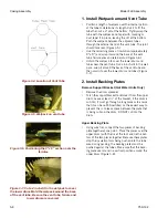
Figure 2- 29: Leak testing the completed pressure
vessel to the boiler design pressure
WARNING -
The assembled Model FLE
pressure vessel is heavy. Until the pressure
vessel is secured to the base, it will be
unstable when standing in an upright position.
Failure to adequately and properly restrain
and/or suspend the drum and tube assembly
prior to securing it to the base may allow the
assembly to fall with the possibility of causing
serious personal injury or death
11. Pressurized Leak Test
After the pressure vessel has been assembled, a
leak test must be performed. The leak test takes as
much time as is needed to check that there are no
leaks. The assembler is responsible for arranging
and preparing for the leak test. An air compressor
capable of pressurizing the flooded pressure vessel
to its design pressure will be required.
If any ferrule-to-drum joint leaks are apparent, the
affected ferrule will need to be driven deeper into
the drum. Relieve the hydraulic pressure, remove
the retainer plate and drive the ferrule deeper into
the drum. Drive the ferrule only far enough to
eliminate leakage.
Table 2- 2: Recommended Pressure for Leak Test
A leak test requires that the following must be
attended to:
• Connection points to the pressure vessel must be
blocked with blind flanges, plugs, or caps
capable of withstanding the required test
pressure.
• A valve capable of withstanding the required test
pressure must be installed in the vent fitting at the
top of the pressure vessel.
• A source of clean water with a minimum
temperature of 70°F must be available to fill the
pressure vessel.
CAUTION -
Before resealing the
ferrules, relieve pressure from the vessel.
Once the ferrules are resealed, repeat the
pressurized leak test.
Figure 2-29. With the vessel flooded and
pressurized, check for leaks at all ferrules and
flanges
Boiler Design
Recommended
Pressure for Leak Test
15 psi Steam
15 psi
150 psi Steam
150 psi
160 psi Hot Water
160 psi
Summary of Contents for FLE
Page 1: ...Model FLE Assembly Instructions 750 192 07 09 Field Erectable Flexible Watertube Boiler ...
Page 4: ...iv Notes ...
Page 8: ...viii ...
Page 16: ...General Description Model FLE Assembly 1 8 750 192 ...
Page 34: ...3 2 750 192 Figure 3 1 Typical Hot Water Flextube Casing ...
Page 36: ...3 4 750 192 Figure 3 2 Typical Low Pressure Steam Flextube Casing ...
Page 38: ...3 6 750 192 Figure 3 3 Typical High Pressure Steam Flextube Casing ...
Page 56: ...Casing Assembly Model FLE Assembly 3 24 750 192 ...
Page 58: ...750 192 4 2 Figure 4 2 Fuel Train Components ...
Page 60: ...4 4 750 192 Figure 4 5 Typical conduit layout ProFire burner on a hot water Flextube boiler ...
Page 61: ...750 192 4 5 Figure 4 6 Typical conduit layout ProFire burner on a steam Flextube boiler ...
Page 62: ...4 6 750 192 Figure 4 7 Nameplate locations hot water boiler ...
Page 63: ...750 192 4 7 Figure 4 8 Nameplate locations steam boiler ...
Page 64: ...e mail info cleaverbrooks com Web Address http www cleaverbrooks com ...


