


750-192
2-9
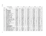
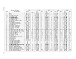
TUBE PATTERNS, STEAM
1 2 3 4 5 6 7 8 9
10 11
Figure 2-18. Tube Patterns - Steam
BOILER SIZE
150-250
300-350
400-600
700-1200
P/N TUBE # 1
93-3200
93-3211
93-3222
93-3233
P/N TUBE # 2
93-3201
93-3212
93-3223
93-3234
P/N TUBE # 3
93-3202
93-3213
93-3224
93-3235
P/N TUBE # 4
93-3203
93-3214
93-3225
93-3236
P/N TUBE # 5
93-3204
93-3215
93-3226
93-3237
P/N TUBE # 6
93-3205
93-3216
93-3227
93-3238
P/N TUBE # 7
93-3206
93-3217
93-3228
93-3239
P/N TUBE # 8
93-3207
93-3218
93-3229
93-3240
P/N TUBE # 9
93-3208
93-3219
93-3230
93-3241
P/N TUBE # 10
93-3209
93-3220
93-3231
93-3242
P/N TUBE # 11
93-3210
93-3221
93-3232
93-3243
Summary of Contents for FLE
Page 1: ...Model FLE Assembly Instructions 750 192 07 09 Field Erectable Flexible Watertube Boiler ...
Page 4: ...iv Notes ...
Page 8: ...viii ...
Page 16: ...General Description Model FLE Assembly 1 8 750 192 ...
Page 34: ...3 2 750 192 Figure 3 1 Typical Hot Water Flextube Casing ...
Page 36: ...3 4 750 192 Figure 3 2 Typical Low Pressure Steam Flextube Casing ...
Page 38: ...3 6 750 192 Figure 3 3 Typical High Pressure Steam Flextube Casing ...
Page 56: ...Casing Assembly Model FLE Assembly 3 24 750 192 ...
Page 58: ...750 192 4 2 Figure 4 2 Fuel Train Components ...
Page 60: ...4 4 750 192 Figure 4 5 Typical conduit layout ProFire burner on a hot water Flextube boiler ...
Page 61: ...750 192 4 5 Figure 4 6 Typical conduit layout ProFire burner on a steam Flextube boiler ...
Page 62: ...4 6 750 192 Figure 4 7 Nameplate locations hot water boiler ...
Page 63: ...750 192 4 7 Figure 4 8 Nameplate locations steam boiler ...
Page 64: ...e mail info cleaverbrooks com Web Address http www cleaverbrooks com ...


