background image

25

4.1 

          I.     Make sure that all the accessories are present according to the list. 
          II.     Make sure that the main console unit is not damaged.
          III.     Make sure that equipment is powered off.
          IV.     For standard rack-mounts, the shorter brackets are required.

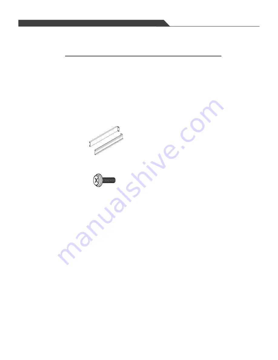
4.2 Hardware Kit Content

         I.    Back rail for 17.72 (450mm)~31.5 (800mm) mounting range.


         III.    Philips screws x 8(For mounting rail to Console unit)


Preparation for installing the Console into the Cabinet

"

"

SECTION 4  INSTALLATION 

1u Claxan KVM-Switch Rack

Summary of Contents for CL-KVM-MPC1700S2-EN

Page 1: ...l Slide LCD Console Series User s Manual CL KVM MPC1700S2 GE CL KVM MPC1700S2 SG PC8 PC7 PC6 PC5 PC4 PC3 PC2 PC1 PROGRAM POWER CL KVM MUX1708S2 EN CL KVM MUX1708S2 GE CL KVM MUX1708S2 SG CL KVM MPC170...

Page 2: ...the installation and operation procedures carefully to prevent any damages to the console unit and or any devices connected to it 1u 17 Rack mount Console 1 pcs 6ft KVM Cable Optional 1 pcs Back rail...

Page 3: ...he installation and operation procedures carefully to prevent any damages to the console unit and or any devices connected to it 1u 17 Rack mount Console 1 pcs 6ft KVM Cable Optional 8 pcs Back rail f...

Page 4: ...on 9 Make sure that the power rating of the outlet matches the unit s 10 Plug the unit to a UPS or surge protector to avoid damage thru electrical surges 11 If in any situation the unit is not used fo...

Page 5: ...sh Buttons 14 2 Hot key Commands 14 3 Using numerical key to select PC 15 4 Press F1 key to activate the AUTO SCAN function 15 5 F2 key SELECT PC function 16 6 F3 key SEARCH PC function 17 7 F4 key ED...

Page 6: ...an auto adjusting and ergonomically designed display We utilize the latest in active thin film transistor TFT technology for all our monitors This provides crisp images and wider viewing angles Compa...

Page 7: ...ipe Display Mode Normally White Brightness cd m 300 center Typ 7 5mA Contrast Ratio 1000 1 typ Support Color 16 7M colors RGB 6 bits FRC data Energy Consumption max 24W Power Supply External 110 240V...

Page 8: ...B Vertical Stripe Display Mode Normally White Brightness cd m 300 center Typ 7 5mA Contrast Ratio 1000 1 typ Support Color 16 7M colors RGB 6 bits FRC data Energy Consumption max 24W Power Supply Ext...

Page 9: ...when on LED indicator for status Green means power on and signal reciept Red means standy suspend or power off Return last menu Status Exit Menu Move cursor up to the function to be adjusted Move curs...

Page 10: ...amma VII Press the Menu button to confirm the selection and the numbers from 0 to 3 on the right are selectable VIII Use the UP Down buttons to scroll down to the wanted number selection and press Men...

Page 11: ...h to another display mode with 4 options on the right Red Green Blue colors with scale and Exit VIII Use the UP Down buttons to scroll down to the wanted color and press the Menu button to confirm the...

Page 12: ...Scroll down to the selection V Position VII Press the Menu button to confirm the selection and the number of scale on the right will turn red from black VIII Use the UP Down buttons to change the num...

Page 13: ...the UP Down buttons to scroll up or down VI Scroll down to the selection Sharpness VII Press the Menu button to confirm the selection and the numbers from 1 to 5 on the right are selectable VIII Use...

Page 14: ...e Menu button to activate the on screen menu II Use the UP Down buttons to scroll up or down III Scroll down to the selection Function IV Press the Menu button to confirm the selection V Use the UP Do...

Page 15: ...II Scroll down to the selection OSD Menu IV Press the Menu button to confirm the selection V Use the UP Down buttons to scroll up or down VI Scroll down to the selection OSD H Pos VII Press the Menu b...

Page 16: ...l down to the selection OSD Menu IV Press the Menu button to confirm the selection V Use the UP Down buttons to scroll up or down VI Scroll down to the selection Translucent VII Press the Menu button...

Page 17: ...down to the selection Misc IV Press the Menu button to confirm the selection V Use the UP Down buttons to scroll up or down VI Scroll down to the selection Reset VII Press the Menu button to confirm t...

Page 18: ...f the main Menu Select the Exit button and press Menu to exit the OSD Menu 2 7 Power Indicator LED light I Green ON II Red Standby III Red Suspend IV Red Off Color Picture Function OSD Menu Misc Exit...

Page 19: ...al PC name and search the PC by name 5 Password setup and management are available If the password is built you must input the correct password to access the target PC 6 AUTO SCAN function is availabl...

Page 20: ...ey 0 9 to select PC F While activating the HOT KEY commands MOUSE will be disable temporarily KEYBOARD can only control the OSD screen but CANNOT control the selected PC G Press ESC to exit the MAIN M...

Page 21: ...der OSD display right side STU field shows the selected PC status selected PC is POWER ON 8 selected PC is daisy chained to 8 port model series which have MASTER SLAVE Configuration D Line one shows P...

Page 22: ...to the MASTER PC SEARCH NAME FIGURE 6 as confirmation For example input PC12345 and hit ENTER to start searching the target PC PC12345 When targeted PC is found it will switch to the PC autocratically...

Page 23: ...ame operation shown as Figure 10 D In Figure 10 the cursor indicates to edit the name of PC2 the cursor becomes the icon prompt to indicate the location you are editing Input at most 16 characters A Z...

Page 24: ...0 Figure 11 MASTER PC mode shown as Figure 9 G Hit ESC to back to the MAIN MENU mode shown as Figure 1 F Figure 11 shows the selected SLAVE PC information hit key to return to the 19 1u Claxan KVM Swi...

Page 25: ...AN will search and switch to the PC which is power on directly b ON After resetting MASTER PC POWER ON SCAN will activate the AUTO SCAN Function the operation step is same as above step 4 F SCAN TIME...

Page 26: ...creen shown as Figure 16 B Under MAIN MENU mode hit F6 key for password editing and if the MASTER password function has been already set the OSD will ask for entering the password of MASTER as Figure...

Page 27: ...move CURSOR and press ENTER to select PC The procedure of PC password Edition is same as step 6 10 Enable Password A If selected PC has setup the password OSD will ask for entering the password of the...

Page 28: ...19 One is to adjust MAIN OSD POSITION The other is to adjust BANNER OSD POSITION Figure 19 B After selecting the choice 1 the screen will enter into MAIN OSD POSITION please refer to Figure 20 By the...

Page 29: ...D If the user would like to go back to the original setting position please press Home key 12 Hit F8 key to enter the screen display HELP This displays the contact information about the manufacturer T...

Page 30: ...e sure that equipment is powered off IV For standard rack mounts the shorter brackets are required 4 2 Hardware Kit Content I Back rail for 17 72 450mm 31 5 800mm mounting range III Philips screws x 8...

Page 31: ...7 72 450mm 31 5 800mm mounting range Philips screws I Well prepare the below items and accessories see below pictures 4 3 Installation for the Console equipped into the Cabinet LCD Consle unit 1u Clax...

Page 32: ...en get the short support ear If the length of A 0 14 3 5mm is over 31 5 800mm please use the long support rear for Installation 27 Figure 1 A IV Screw the back rail which would be fixed with LCD conso...

Page 33: ...the guide of the unit both side of LCD console unit into the 2 back rails And push the console to the end of back and screw the front rail to the proper position of the rackrail of the cabinet See Fi...

Page 34: ...29 VI Finish installation by connecting cables and power cord See figure 4 Figure 4 1u Claxan KVM Switch Rack...

Page 35: ......

Reviews: