background image

Table of Contents

Preface . . . . . . . . . . . . . . . . . . . . . . . . . . . . . . . . . . . . . . . . . . . . . . . . . . . . . . . . . . . . . . . . . . . . . . . . . . . . . . . . . . . . . . . . . . . . . . . . . . . . . . . . . . . . . . . . 5
1. E20 Product Overview . . . . . . . . . . . . . . . . . . . . . . . . . . . . . . . . . . . . . . . . . . . . . . . . . . . . . . . . . . . . . . . . . . . . . . . . . . . . . . . . . . . . . . . . 7

1.1. Unpacking the E20 . . . . . . . . . . . . . . . . . . . . . . . . . . . . . . . . . . . . . . . . . . . . . . . . . . . . . . . . . . . . . . . . . . . . . . . . . . . . . . . . . . 7
1.2. Interfaces and Ports . . . . . . . . . . . . . . . . . . . . . . . . . . . . . . . . . . . . . . . . . . . . . . . . . . . . . . . . . . . . . . . . . . . . . . . . . . . . . . . . . 9

2. Registering with Clavister . . . . . . . . . . . . . . . . . . . . . . . . . . . . . . . . . . . . . . . . . . . . . . . . . . . . . . . . . . . . . . . . . . . . . . . . . . . . . . . . . . 11
3. E20 Installation . . . . . . . . . . . . . . . . . . . . . . . . . . . . . . . . . . . . . . . . . . . . . . . . . . . . . . . . . . . . . . . . . . . . . . . . . . . . . . . . . . . . . . . . . . . . . . . . . 16

3.1. General Installation Guidelines . . . . . . . . . . . . . . . . . . . . . . . . . . . . . . . . . . . . . . . . . . . . . . . . . . . . . . . . . . . . . . . . . 16
3.2. Flat Surface Installation . . . . . . . . . . . . . . . . . . . . . . . . . . . . . . . . . . . . . . . . . . . . . . . . . . . . . . . . . . . . . . . . . . . . . . . . . . . 18
3.3. Rack Mounting . . . . . . . . . . . . . . . . . . . . . . . . . . . . . . . . . . . . . . . . . . . . . . . . . . . . . . . . . . . . . . . . . . . . . . . . . . . . . . . . . . . . . . 19
3.4. Mini-USB Console Port Connection . . . . . . . . . . . . . . . . . . . . . . . . . . . . . . . . . . . . . . . . . . . . . . . . . . . . . . . . . . . 21
3.5. Connecting Power . . . . . . . . . . . . . . . . . . . . . . . . . . . . . . . . . . . . . . . . . . . . . . . . . . . . . . . . . . . . . . . . . . . . . . . . . . . . . . . . . . 23

4. cOS Core Configuration . . . . . . . . . . . . . . . . . . . . . . . . . . . . . . . . . . . . . . . . . . . . . . . . . . . . . . . . . . . . . . . . . . . . . . . . . . . . . . . . . . . . . 26

4.1. Management Workstation Connection . . . . . . . . . . . . . . . . . . . . . . . . . . . . . . . . . . . . . . . . . . . . . . . . . . . . . . 26
4.2. Web Interface and Wizard Setup . . . . . . . . . . . . . . . . . . . . . . . . . . . . . . . . . . . . . . . . . . . . . . . . . . . . . . . . . . . . . . . 29
4.3. Manual Web Interface Setup . . . . . . . . . . . . . . . . . . . . . . . . . . . . . . . . . . . . . . . . . . . . . . . . . . . . . . . . . . . . . . . . . . . . 37
4.4. CLI Setup . . . . . . . . . . . . . . . . . . . . . . . . . . . . . . . . . . . . . . . . . . . . . . . . . . . . . . . . . . . . . . . . . . . . . . . . . . . . . . . . . . . . . . . . . . . . . . 53
4.5. License Installation Methods . . . . . . . . . . . . . . . . . . . . . . . . . . . . . . . . . . . . . . . . . . . . . . . . . . . . . . . . . . . . . . . . . . . . 61
4.6. Setup Troubleshooting . . . . . . . . . . . . . . . . . . . . . . . . . . . . . . . . . . . . . . . . . . . . . . . . . . . . . . . . . . . . . . . . . . . . . . . . . . . 63
4.7. Going Further with cOS Core . . . . . . . . . . . . . . . . . . . . . . . . . . . . . . . . . . . . . . . . . . . . . . . . . . . . . . . . . . . . . . . . . . . . 65

5. Resetting to Factory Defaults . . . . . . . . . . . . . . . . . . . . . . . . . . . . . . . . . . . . . . . . . . . . . . . . . . . . . . . . . . . . . . . . . . . . . . . . . . . . . . 68
6. Warranty Service . . . . . . . . . . . . . . . . . . . . . . . . . . . . . . . . . . . . . . . . . . . . . . . . . . . . . . . . . . . . . . . . . . . . . . . . . . . . . . . . . . . . . . . . . . . . . . 70
7. Safety Precautions . . . . . . . . . . . . . . . . . . . . . . . . . . . . . . . . . . . . . . . . . . . . . . . . . . . . . . . . . . . . . . . . . . . . . . . . . . . . . . . . . . . . . . . . . . . . 72
A. E20 Specifications . . . . . . . . . . . . . . . . . . . . . . . . . . . . . . . . . . . . . . . . . . . . . . . . . . . . . . . . . . . . . . . . . . . . . . . . . . . . . . . . . . . . . . . . . . . . 75

3

Summary of Contents for Eagle E20

Page 1: ...Clavister Eagle E20 Getting Started Guide Clavister AB Sjögatan 6J SE 89160 Örnsköldsvik SWEDEN Phone 46 660 299200 www clavister com Published 2016 01 13 Copyright 2016 Clavister AB ...

Page 2: ...Clavister reserves the right to revise this publication and to make changes from time to time in the content hereof without any obligation to notify any person or parties of such revision or changes Limitations of Liability UNDER NO CIRCUMSTANCES SHALL CLAVISTER OR ITS SUPPLIERS BE LIABLE FOR DAMAGES OF ANY CHARACTER E G DAMAGES FOR LOSS OF PROFIT SOFTWARE RESTORATION WORK STOPPAGE LOSS OF SAVED D...

Page 3: ...Mounting 19 3 4 Mini USB Console Port Connection 21 3 5 Connecting Power 23 4 cOS Core Configuration 26 4 1 Management Workstation Connection 26 4 2 Web Interface and Wizard Setup 29 4 3 Manual Web Interface Setup 37 4 4 CLI Setup 53 4 5 License Installation Methods 61 4 6 Setup Troubleshooting 63 4 7 Going Further with cOS Core 65 5 Resetting to Factory Defaults 68 6 Warranty Service 70 7 Safety ...

Page 4: ... Unpacked Clavister E20 Appliance 7 1 2 Clavister E20 Connection Ports 9 1 3 The E20 Ethernet Interface Ports 9 3 1 The E20 Mini USB Local Console Port 21 3 2 Rear view of the Clavister E20 23 3 3 E20 Power Inlet Socket 23 4 ...

Page 5: ... side of the page followed by a short paragraph in italicized text There are the following types of such sections Note This indicates some piece of information that is an addition to the preceding text It may concern something that is being emphasized or something that is not obvious or explicitly stated in the preceding text Tip This indicates a piece of non critical information that is useful to...

Page 6: ...http www clavister com Trademarks Certain names in this publication are the trademarks of their respective owners cOS Core is the trademark of Clavister AB Windows Windows XP Windows Vista Windows 7 Windows 8 and Windows 10 are either registered trademarks or trademarks of Microsoft Corporation in the United States and or other countries Apple Mac and Mac OS are trademarks of Apple Inc registered ...

Page 7: ...the unpacking of the E20 appliance Open the packaging box used for shipping and carefully unpack the contents The delivered product packaging should contain the following The Clavister E20 appliance Mini USB local console cable Power cable A rack mount kit consisting of screws and 2 brackets suitable for a 19 inch rack Attachable rubber feet for flat surface installation 7 ...

Page 8: ...the E20 can be downloaded from the E20 product page which can be found by going to http www clavister com start and selecting the E20 link End of Life Treatment The E20 appliance is marked with the European Waste Electrical and Electronic Equipment WEEE directive symbol which is shown below The product and any of its parts should not be discarded using a regular refuse disposal method At end of li...

Page 9: ...ces are connected together by a common switch fabric and share the single logical cOS Core interface name GS This means that any security policy in the cOS Core rule sets that refers to the interface GS will apply to traffic on any of the 4 physical interfaces Note The two USB Type A ports are not currently used The two USB Type A ports on the E20 front panel are for future functionality and are n...

Page 10: ...Chapter 1 E20 Product Overview 10 ...

Page 11: ...S Core wizard the wizard will provide a link to the registration page so it can be done while the wizard is running Registration of the E20 Hardware Unit This is mandatory for every hardware unit before a license can be downloaded It can be done in the following ways i Automatic registration after cOS Core starts This can done by the Setup Wizard which starts automatically in a browser popup windo...

Page 12: ...on webpage is now presented The required information should be filled in In the example below a user called John Smith registers It is important to enter the administrator s company details as well Without company details a license cannot be created 4 When the registration details are accepted an email is sent to the email address given so that the registration can be confirmed Chapter 2 Registeri...

Page 13: ...w customer is taken to a webpage to indicate that confirmation has been successful They should now log in to the Clavister website with the credentials they have submitted during registration 7 After logging in the website toolbar will show the name of the currently logged in customer Chapter 2 Registering with Clavister 13 ...

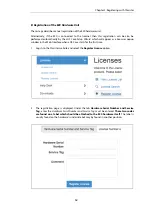
Page 14: ... Web Interface when cOS Core starts for the first time 1 Log in to the Clavister website and select the Register License option 2 The registration page is displayed Under the tab Hardware Serial Number and Service Tag enter the Hardware Serial Number and Service Tag must be entered These two codes are found on a label which should be attached to the E20 hardware itself The label is usually found o...

Page 15: ...r download and installation from Clavister servers This installation can be done automatically through the cOS Core Setup Wizard which is described in Section 4 2 Web Interface and Wizard Setup If the E20 is not connected to the Internet the license must be manually downloaded from the cOS Core website and then manually uploaded All license installation options are listed and discussed in Section ...

Page 16: ...appliance to connect it to the power source Using Other Power Cords If your installation requires a different power cord than the one supplied with the appliance be sure to use a cord displaying the mark of the safety agency that defines the regulations for power cords in your country Such marks are an assurance that the cord is safe Power Overload Ensure that the appliance does not overload the p...

Page 17: ...mperature range is room temperature That is to say the temperature most commonly found in a modern office and in which humans feel comfortable This is usually considered to be between 20 and 25 degrees Celsius 68 to 77 degrees Fahrenheit Special rooms for computer equipment may use a lower range and this is also acceptable Airflow Make sure that airflow around the appliance is not restricted Note ...

Page 18: ... a flat surface This protects both the surface and the appliance from external damage as well as allowing air to circulate underneath for improved cooling during operation Important Always leave space around the appliance Always ensure there is adequate space around the appliance for ventilation and access to operating switches and cable connectors No objects should be placed on top of the casing ...

Page 19: ...acket to one side of the E20 The kit is attached to the sides of the E20 unit prior to mounting in the rack There are pre drilled holes in each bracket and in the side of the E20 as shown below Align the bracket screw holes with the pre drilled holes on the side of the E20 Then fit and tighten the supplied screws into the holes with a suitable screwdriver as shown below Chapter 3 E20 Installation ...

Page 20: ...Repeat this for each side of the E20 so the brackets are mounted as shown below The E20 is now ready to be rack mounted No rear support is required Chapter 3 E20 Installation 20 ...

Page 21: ...on computer running console emulation software 3 After connection to a PC Windows will try to recognize the device and automatically install the appropriate driver through the Windows Update feature If Windows is unable to do this automatically the driver should be downloaded and installed manually For the Linux and MacOS micro USB drivers or to download the Windows driver manually go to the E20 p...

Page 22: ...password is recommended A local console password need not be set However if it is not anyone with physical access to the local console will have full administrator rights Unless the hardware is placed in a secure area it is therefore recommended to set a local console password This is done by entering the console boot menu at system startup by pressing any console key before cOS Core has fully sta...

Page 23: ...end of the power cord into the power inlet socket on the E20 Figure 3 3 E20 Power Inlet Socket 2 Plug the other end of the power cord into a grounded power outlet 3 Power is controlled by a rocker switch situated to the left of the power inlet socket To switch on depress the upper part of the switch so move it moves to the On position 4 The E20 will boot up as soon as power is applied and cOS Core...

Page 24: ...ate surge protection unit from a third party is considered for the power connection to the E20 hardware This is to ensure that the E20 is protected from damage by sudden external electrical power surges through the power cable Surge protection is particularly important in locations where there is a heightened risk of lightning strikes and or power grid spikes Any surge protection unit should be in...

Page 25: ...Chapter 3 E20 Installation 25 ...

Page 26: ...and will automatically boot up after power is applied After boot up is complete an external management computer workstation can be used to configure cOS Core The management computer s operating system can be any kind as long it can run a web browser The Default Management Interface After first time startup cOS Core automatically makes management access available on a single predefined Ethernet int...

Page 27: ...physical Ethernet interface This is a similar to the connection used with the Web Interface and is also done using the default management interface after powering up for the first time ii Alternatively CLI access can be through console emulation software running on a Windows based computer connected directly to the mini USB port on the E20 hardware Direct console connection is described in Section...

Page 28: ...for the Ethernet interface used for connection on the management workstation is that DHCP is enabled cOS Core automatically enables a DHCP server on the security gateway s GS interfaces numbered 1 to 4 and this allocates the required IP addresses to the management computer using DHCP If the management computer is configured manually the following settings should be used IP address 192 168 1 30 Sub...

Page 29: ...ed by the administrator but this is not recommended Connect By Browsing to https 192 168 1 1 Using a web browser enter the address https 192 168 1 1 into the navigation window as shown below Important Disable any proxy server and turn off popup blocking Make sure the web browser doesn t have a proxy server configured The wizard runs in a browser popup window The popup must be allowed for the setup...

Page 30: ... Login Dialog cOS Core will next respond like a web server with the initial login dialog page as shown below The available Web Interface language options are selectable at the bottom of this dialog This defaults to the language set for the browser if cOS Core supports that language Enter the administrator username admin and default password admin The Setup Wizard After login the Web Interface will...

Page 31: ...ained in the two sections that follow Advantages of the Wizard The wizard makes setup easier because it automates what would otherwise be a more complex set of individual setup steps It also reminds you to perform important tasks such as setting the date and time and configuring a log server The steps that the wizard goes through after the welcome screen are listed next Wizard step 1 Enter a new u...

Page 32: ...that will be used to connect to an ISP for Internet access Wizard step 4 Select the WAN interface settings This step selects how the WAN connection to the Internet will function It can be one of Manual configuration DHCP PPPoE or PPTP as shown below Chapter 4 cOS Core Configuration 32 ...

Page 33: ...ary DNS server field 4B DHCP automatic configuration All required IP addresses will automatically be retrieved from the ISP s DHCP server with this option No further configuration is required for this so it does not have its own wizard screen 4C PPPoE settings The username and password supplied by an ISP for PPPoE connection should be entered The Service field should be left blank unless the ISP s...

Page 34: ...ion with PPTP Wizard step 5 DHCP server settings If the Clavister Security Gateway is to function as a DHCP server it can be enabled here in the wizard on a particular interface or configured later The range of IPv4 addresses that can be handed out must be specified in the form n n n n n n n n where n is a number between 0 and 255 and n n n n is a valid IPv4 address within a subnet local to the se...

Page 35: ...S Core For the default gateway it is recommended to specify the IPv4 address assigned to the internal network interface In this setup this corresponds to 192 168 1 1 The DNS server specified should be the DNS supplied by an ISP When specifying a hostname as a server instead of an IP address the hostname should be prefixed with the string dns For example the hostname host1 company com should be ent...

Page 36: ...n After registration come back to this step Alternatively this step can be skipped and license installation can be done later in which case cOS Core will run in demo mode with a 2 hour time limit After the 2 hour period only management access will be allowed If a license is installed at this point the wizard will then ask if a reconfigure or restart operation should be performed If all license par...

Page 37: ... Core interfaces are logically equal for cOS Core and although their physical capabilities may be different any interface can perform any logical function With the E20 any of the physical GS interfaces can act as the default management interface The other interfaces can be used as required For this section it is assumed that the G2 interface will be used for connection to the public Internet and t...

Page 38: ...Activate option from the Configuration menu this procedure is also referred to as deploying a configuration A dialog is then presented to confirm that the new configuration is to become the running configuration After clicking OK cOS Core reconfiguration will take place and after a short delay the Web Interface will try and connect again to the security gateway If no reconnection is detected by cO...

Page 39: ...y log the user out If they log back in through the same web browser session then they will return to the point they were at before the logout occurred and no saved but not yet activated changes are lost Setting Up Internet Access Next we shall look at how to set up public Internet access The setup wizard described in the previous chapter provides the following four options A Static manual configur...

Page 40: ... 4 1 The ISP s gateway is the first router hop towards the public Internet from the Clavister Security Gateway Go to Objects Address Book in the Web Interface The current contents of the address book will be listed and will contain a number of predefined objects automatically created by cOS Core after it scans the interfaces for the first time The screenshot below shows the initial address book fo...

Page 41: ...ders New folders can be created when needed and provide a convenient way to group together related IP address objects The folder name can be chosen to indicate the folder s contents Now click the Add button at the top left of the list and choose the IP4 Address option to add a new address to the folder Enter the details of the object into the properties fields for the IP4 Address object Below the ...

Page 42: ...fault Gateway which is the ISP s router must be specified As explained in more detail later specifying the Default Gateway also has the additional effect of automatically adding a route for the gateway in the cOS Core routing table At this point the connection to the Internet is configured but no traffic can flow to or from the Internet since all traffic needs a minimum of the following two cOS Co...

Page 43: ...e any traffic controlled by a NAT rule will be controlled by the cOS Core state engine This means that the rule will allow connections that originate from the source network destination and also implicitly allow any returning traffic that results from those connections In the above the predefined service called http is the best service to use for web browsing this service includes HTTP and HTTPS b...

Page 44: ...rface where the network all nets in other words any network will be found If the default main routing table is opened by going to Network Routing Routing Tables main the route needed should appear as shown below This required all nets route is in fact added automatically after specifying the Default Gateway for a particular Ethernet interface and this was done earlier when setting up the required ...

Page 45: ...omatically from the ISP via DHCP and cOS Core automatically sets the relevant address objects in the address book with this information For cOS Core to know on which interface to find the public Internet a route has to be added to the main cOS Core routing table which specifies that the network all nets can be found on the interface connected to the ISP and this route must also have the correct De...

Page 46: ...k Routing Routing Tables main we can see this route If the PPPoE tunnel object is deleted this route is also automatically deleted At this point no traffic can flow through the tunnel since there is no IP rule defined that allows it As was done in option A above we must define an IP rule that will allow traffic from the source network G1_net and source interface to flow to the destination network ...

Page 47: ... deleted At this point no traffic can flow through the tunnel since there is no IP rule defined that allows it As was done in option A above we must define an IP rule that will allow traffic from a designated source network and source interface in this example the network G1_net and interface G1 to flow to the destination network all nets and the destination interface which is the PPTP tunnel that...

Page 48: ...ould be set for example to be the IPv4 address object dns1_address Syslog Server Setup Although logging may be enabled no log messages are captured unless at least one log server is set up to receive them and this is configured in cOS Core Syslog is one of the most common server types First we create an IP4 Address object called for example syslog_ip which is set to the IPv4 address of the server ...

Page 49: ...r the cOS Core will drop any traffic unless an IP rule explicitly allows it Let us suppose that we wish to allow the pinging of external hosts with the ICMP protocol by computers on the internal G1_net network There can be several rule sets defined in cOS Core but there is only one rule set defined by default and this is called main To add a rule to it first select Policies Firewalling Main IP Rul...

Page 50: ... is found for a new connection then the default rule is triggered This rule is hidden and cannot be changed and its action is to drop all such traffic as well as generate a log message for the drop In order to gain control over the logging of dropped traffic it is recommended to create a drop all rule as the last rule in the main IP rule set This rule has an Action of Drop with the source and dest...

Page 51: ...n Objects If information is deleted from a configuration during editing then these deletions are indicated by a line scored through the list entry while the configuration is still not yet activated The deleted entry only disappears completely when the configuration changes are activated For example we can delete the Drop_All IP rule created previously by right clicking the IP rule and selecting De...

Page 52: ...hour demo mode limitation Without a license installed cOS Core will have full functionality during the 2 hour period following startup but after that only management access will be possible Installing a license is described in Section 4 5 License Installation Methods Chapter 4 cOS Core Configuration 52 ...

Page 53: ...a normal CLI prompt if connecting directly through the local console port and a username password combination will not be required a password for this console can be set later Device If connecting remotely through an SSH Secure Shell client an administration username password must first be entered and the initial default values for these are username admin and password admin When these are accepte...

Page 54: ...after initial startup All cOS Core interfaces are logically equal for cOS Core and although their physical capabilities may be different any interface can perform any logical function With the E20 any of the physical GS interfaces can act as the default management interface The other interfaces can be used as desired For this section it is assumed that the G2 interface will be used for connection ...

Page 55: ... creates and fills the InterfaceAddresses folder in the cOS Core address book with Ethernet interface related IPv4 address objects When an IP address object which is located in a folder is specified in the CLI the object name must be qualified with the name of its parent folder For example to reference the address G2_ip it must be qualified with the folder name InterfaceAddresses so it becomes Int...

Page 56: ...ddresses In that case we must use NAT to send out traffic so that the apparent source IP address is the IP of the interface connected to the ISP To do this we simply change the Action property in the above command from a value of Allow to a value of NAT Device main add IPRule Action NAT SourceInterface G1 SourceNetwork InterfaceAddresses G1_net DestinationInterface G2 DestinationNetwork all nets S...

Page 57: ...ve we must therefore manually define an IP rule that will allow traffic from a designated source network and source interface in this example the network G1_net and interface G1 to flow to the destination network all nets and the destination interface G2 C PPPoE setup For PPPoE connection create the PPPoE tunnel interface on the interface connected to the ISP The interface G2 is assumed to be conn...

Page 58: ...hen this route is also automatically deleted At this point no traffic can flow through the tunnel since there is no IP rule defined that allows it As was done in option A above we must define an IP rule that will allow traffic from a designated source network and source interface in this example the network G1_net and interface G1 to flow to the destination network all nets and the destination int...

Page 59: ...sets up synchronization with the two NTP servers at hostname pool ntp org and IPv4 address 10 5 4 76 Device set DateTime TimeSyncEnable Yes TimeSyncServer1 dns pool ntp org TimeSyncServer2 10 5 4 76 The prefix dns is added to the hostname to identify that it must resolved to an IP address by a DNS server this is a convention used in the CLI with some commands Syslog Server Setup Although logging m...

Page 60: ...n control over the logging of dropped traffic it is recommended to create a drop all rule as the last rule in the main IP rule set This rule has an Action of Drop with the source and destination network set to all nets and the source and destination interface set to any The service for this rule must also be specified and this should be set to all_services in order to capture all types of traffic ...

Page 61: ...ister website then press Activate The license is fetched automatically across the public Internet and installed This method is also only available when installing a license for the first time Automatically through the CLI In the CLI enter the command Device license activate request username myname password mypass The customer username and password login are included in the command and the license ...

Page 62: ...ense through the Web Interface or the startup wizard the option to restart will be presented When using the CLI or SCP for installation restarting is done in the Web Interface by going to Status Maintenance Reset Restore With the CLI use the command Device shutdown reboot Installing Future Licenses As mentioned above fetching the license automatically using the setup wizard Web Interface or CLI is...

Page 63: ...t obvious problem is if the IP address of the management computer is not configured correctly 4 Is the management interface properly connected Check the link indicator lights on the management interface If they are dark then there may be a cable problem 5 Using the ifstat CLI command To investigate a connection problem further connect the a console to the local console port on the Clavister Securi...

Page 64: ...rfaces and confirm that the correct cables are connected to the correct interfaces To look at the ARP activity only a particular interface follow the command with the interface name Device arpsnoop interface To switch snooping off use the command Device arpsnoop none Chapter 4 cOS Core Configuration 64 ...

Page 65: ...ions of the source destination interface network combined with protocol type By default no IP rules are defined so all traffic is dropped At least one IP rule needs to be defined before traffic can traverse the Clavister Security Gateway An alternative to IP Rule objects is to use IP Policy objects These have essentially the same function but simplify the setting up of address translation and the ...

Page 66: ...I Reference Guide provides a complete listing of the available CLI commands with their options A CLI overview is also provided as part of the cOS Core Administration Guide cOS Core Education Courses For details about classroom and online cOS Core education as well as cOS Core certification visit the Clavister company website at http www clavister com or contact your local sales representative Stay...

Page 67: ...Chapter 4 cOS Core Configuration 67 ...

Page 68: ...rdware startup These two options are described in detail below Caution cOS Core upgrades and current configuration are lost The factory defaults will include the default configuration and the original version of cOS Core that the product left the factory with Any cOS Core upgrades that have been installed will be lost This means Any cOS Core upgrades that have been performed since the product left...

Page 69: ...onsole display window connected to the E20 local console port 2 Power off the E20 3 Push in the recessed reset button on the front of the E20 with a suitable pointed tip tool A paper clip could be used The recessed unlabeled pinhole button is directly to the right of the E20 Ethernet ports 4 Holding the button in power up the E20 5 Continue holding in the button for at least 30 seconds longer afte...

Page 70: ...ny other misuse Any replacement Hardware will be warranted for the remainder of the original warranty period or thirty days whichever is longer Note that the term Start Date means the earlier of the product registration date OR ninety 90 days following the day of shipment by Clavister Obtaining Warranty Service with an RMA Warranty service can be obtained within the warranty period with the follow...

Page 71: ...y of the software firmware information or memory data contained in stored on or integrated with any product returned to Clavister pursuant to a warranty claim Contacting Clavister Should there be a problem with the online form then Clavister support can be contacted by going to https www clavister com support Customer Remedies Clavister s entire liability according to this warranty shall be at Cla...

Page 72: ...viceable parts inside these products Only service trained personnel can perform any adjustment maintenance or repair Säkerhetsföreskrifter Dessa produkter är säkerhetsklassade enligt klass I och har anslutningar för skyddsjord En obruten skyddsjord måste finnas från strömkällan till produktens nätkabelsanslutning eller nätkabel Om det finns skäl att tro att skyddsjorden har blivit skadad måste pro...

Page 73: ... Hauptstromquelle zu den Geräteingabeterminals den Netzkabeln oder dem mit Strom belieferten Netzkabelsatz voraus Sobald Grund zur Annahme besteht dass der Schutz beeinträchtigt worden ist das Netzkabel aus der Wandsteckdose herausziehen bis die Erdung wiederhergestellt ist Für LAN Kabelerdung Wenn Ihr LAN ein Gebiet umfasst das von mehr als einem Stromverteilungssystem beliefert wird müssen Sie s...

Page 74: ...orna de puesta a tierra Es preciso que exista una puesta a tierra continua desde la toma de alimentacíon eléctrica hasta las bornas de los cables de entrada del aparato el cable de alimentación hasta haberse subsanado el problema Puesta a tierra del cable de la red local LAN Si la LAN abarca un área cuyo suministro eléctrico proviene de más de una red de distribución de electricidad cerciorarse de...

Page 75: ... CE class A Environmental Operating and Storage Humidity 0 to 90 non condensing Operating Temperature 5 to 45 C Random vibration operating 10 500 Hz 2G 10min 1 cycle period for 60min Power Specifications Power Supply AC 100 240 VAC 50 60 Hz 3 1 5 A Typical Power Consumption 12 W BTU 127 BTU PSU Rated Power 25 W Ethernet Interface Support Gigabit RJ45 interfaces Automatic MDI X 1000BASE T copper RJ...

Page 76: ...Clavister AB Sjögatan 6J SE 89160 Örnsköldsvik SWEDEN Phone 46 660 299200 www clavister com ...

Reviews: