


T H E C O N T I N U O U S P O W E R C O M P A N Y
Page 7
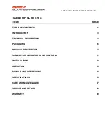
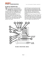
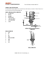
PHYSICAL DESCRIPTION
his section will point out and illustrate the
various indicators, functions and controls of
the
SN Series
UPS. Pictured is the front view
of the system, then followed by the rear view.
The important attributes of the
SN Series
unit are
numbered to assist you in locating them on your
machine and also to fully explain its function and
how it relates to system operation.
Numbers on the drawing will correspond to the
operating component’s name at the bottom with a
brief identification. In the next section, a complete
explanation of all numbered items will be enhanced
to ensure you have a full understanding of the
operation of this system.
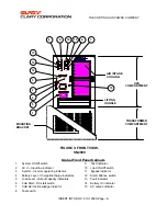
Visual indicators used on the front panel are long
lasting, very efficient, light emitting diodes (LED).
When operating the push-button switches, always
hold the switch in for at least two seconds to insure
function confirmation. This feature has been
implemented into the system design to avoid
inadvertent operation of any of the user-available
functions.
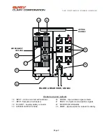
The rear panel has been engineered with the user’s
multiple applications in mind. In some models, two
of the output receptacles have been rotated to allow
attachment of a plug-in transformer without hanging
over the back of the unit or interfering with another
outlet. The outputs can be switched on or off.
T
6
8
7
10
9
1
2
3
14
11
12
13
4
5
AIR INTAKE,
COOLING
LIFTING
HANDLE
FIGURE 2: FRONT VIEW, SN1000
15


