


THE CONTINUOUS POWER COMPANY
SUMMARY OF INDICATORS AND CONTROLS
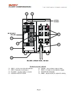
INPUT POWER
-
This is system input AC power
protection and interruption for both hot and neutral
lines. This is a circuit breaker that if tripped, unit
operation will continue on battery reserve. This
circuit breaker is rated at 20A.
SYSTEM ON/OFF
-
This is system input enable
switch. This switch is used to power down the
system. This switch must be in the
ON
position in
order to AC or DC start the UPS.
LOAD
- Four green L.E.D.s and one red
OVERLOAD L.E.D. that illuminate to update status
of the amount of load the INVERTER is powering at
the UPS system output. Each green L.E.D.
represents approximately 25% of full load. As more
load is added to the UPS, the L.E.D.s will
sequentially turn
"ON"
until the red L.E.D. comes
"ON"
. This indicates an OVERLOAD situation and
the system will discontinue operation shortly.
BATTERY
- Four green L.E.D.s and one green
LOW BATTERY L.E.D. that illuminate to update
status of the battery energy available during a power
outage. Each green L.E.D. represents
approximately 20% of battery reserve power
available. As battery discharge continues, the
L.E.D.s will sequentially turn
"OFF"
until the last
L.E.D. starts to flash. This indicates a LOW
BATTERY situation and the system will discontinue
operation shortly. Once utility power is returned to
the system, this bar graph will show an approximate
battery state as it reaches full charge.
AC IN
- A green L.E.D. that is illuminated when both
the
INPUT POWER
Circuit Breaker and the
SYSTEM ON/OFF
switch are closed and there is
utility power present at the input of the system.
BATTERY ON
- A red L.E.D. that is illuminated
when the AC input is interrupted to the power
electronics either externally or internally from the
microprocessor due to an out-of-range situation.
The output load is then supported entirely by battery
energy through INVERTER operation.
INV
-
A green L.E.D. that illuminates when the
INVERTER generator is operating and available to
deliver power to the system output.
COLD START
-
This is a momentary, two position
push button keyswitch. If no AC utility voltage is
available, it may still be a requirement to initialize
some equipment. When this switch is pressed in for
at least two seconds, the system will start up on
battery power. The
SYSTEM
ON/OFF
Switch must
be in the
ON
position for this function to operate.
The green L.E.D. above this switch will light only
while the switch is held in.
LOAD ON/OFF
- This is a momentary, two-
position push button keyswitch. When the system
initially powers up for the first time no INVERTER
generator power will be present at the output load
receptacles at the rear panel. Once this switch is
pressed in for at least two seconds, output power
will then be enabled to the rear panel outlets. If the
system should be powered down for any reason
other than with the
SYSTEM
ON/OFF
Switch, the
output state of these outlets will be remembered by
the internal microprocessor and the UPS will start up
with the output in the state it was last left. The
output neon lamp, in the center of the panel, will light
when the output has been enabled.
BYPASS
- A red L.E.D. above the
AC OUTPUT
Switch will light to indicate when the system output
is operating in the filtered, emergency BYPASS
mode. This is an unprotected power source that will
not support the load in the event of a power failure.
SILENCE
- This is a momentary, two position push
button keyswitch. During a system
FAULT
or power
failure, an audible alarm will be present. If a
FAULT
condition occurs, the red L.E.D. above this switch
will light. Once this switch is pressed in for at least
two seconds, the audible alarm will be silenced. The
L.E.D. above the switch will remain unchanged.
TEST -
This is a momentary, two position push
button keyswitch. Battery condition is vital to the
UPS performance, particularly during a power
outage. During normal operation and if the Battery
Bar Graph shows the battery at a full charge, this
function switch may be used. By pressing this
switch in for at least two seconds, a battery
acceptance diagnostic will be run by the internal
microprocessor. If it has been discovered that the
battery is excessively fatigued, the red L.E.D. above
this switch will light advising the user to replace the
internal battery or DC supply. The system will run
this test on its own approximately every 24 hours.
INSERT INTO DOC. 510-12580-Page –11-


