Clary Corporation SN1000 Owners Operating & Maintenance Manual Download Page 19

T H E   C O N T I N U O U S   P O W E R   C O M P A N Y

Page 19

WARRANTY

1. TIME AND SCOPE OF WARRANTY:

1.1 CIary Corporation hereby warrants all equipment shipped under this Agreement to be free from defective components and

workmanship for a period of 2 years following date of shipment.  Accidental damage, misuse or normal wear shall not be
construed as a defect.

1.2 The date of shipment as used herein will be the date on Clary’s Bill of Lading.  If no Bill of Lading is issued, the date of

shipment shall be shown on seller's shipping document.

1.3 No provision of this warranty shall cover equipment, which has been altered or modified from the original specifications to

which same was manufactured, unless authorized in writing.

2. LIMITS OF "IN-WARRANTY" SERVICE LIABILITY

2.1 Clary is obligated for two (2) years following date of shipment to replace any parts from equipment returned to the factory

which, in the opinion of authorized Clary personnel, are found to have been defective (the term "factory" as used herein
shall also include any field service centers which may be established by Clary). Clary is obligated for two (2) years following
date of shipment to provide service and/or adjustments to equipment returned to the factory.  Batteries are guaranteed for a
period of one (1) year.  The cost of shipping equipment to or from the factory is not covered under this warranty.

2.2 Equipment requiring in-warranty service must be returned to the factory with all transportation charges prepaid.  Equipment

must be clearly tagged stating the nature of the trouble experienced and the disposition of the equipment after repair.  The
equipment will be returned freight collect by Clary to the location specified via the best, least expensive carrier available, or
via customer's shipping instructions.

2.3 The nature of certain equipment installations may be such that it would be impractical or technically infeasible to remove

the Clary portion of the equipment from the customer's premises to the Clary factory.  In such cases, and at the request of
the buyer, Clary will perform such service as can be satisfactorily rendered at buyers location.  When equipment startup is
performed by Clary personnel, the buyer will be charged only for travel expenses incidental to the service call, provided that
the warranty is applicable.  When equipment startup is not performed by Clary personnel, travel time will also be charged.

2.4 During the in-warranty period, no service charges shall be payable by the buyer for service performed other than for

service necessitated by accident, misuse, theft, abnormal line or source voltage fluctuations, abnormal conditions of
operation, damage by the elements or damage resulting from adjustments, repairs, modifications made by other than Clary
Authorized personnel, or the buyer's failure to reasonably maintain the equipment

THE FOREGOING WARRANTY IS EXCLUSIVE AND IS GIVEN AND ACCEPTED IN LIEU OF ANY AND ALL OTHER
WARRANTIES, EXPRESSED OR IMPLIED. INCLUDING WITHOUT LIMITATION THE IMPLIED WARRANTIES OF
MERCHANTABILITY AND FITNESS FOR A PARTICULAR PURPOSE.  THE REMEDIES OF BUYER SHALL BE LIMITED
TO THOSE PROVIDED HEREIN.  IN NO EVENT WILL SELLER BE LIABLE FOR COLLATERAL OR CONSEQUENTIAL
DAMAGES.  No person is authorized to assume in behalf of Clary any obligation or liability in connection with the sale,
warranty or service policy of any products manufactured and/or marketed by Clary Corporation beyond the warranty
description on the face hereof.

3.1 Clary Corporation reserves the right to make changes, additions. and/or improvements in its products without incurring any

obligation to install them on its products previously sold.

Summary of Contents for SN1000

Page 1: ...of Clary Corporation is proprietary confidential and not to be disclosed disseminated or used except for the purpose provided by CLARY CORPORATION P N 510 12580 A RD 12 29 03 Manufactured by T H E C...

Page 2: ...LE PAGE TABLE OF CONTENTS 1 INTRODUCTION 3 TECHNICAL DESCRIPTION 4 PACKAGING 6 PHYSICAL DESCRIPTION 7 SUMMARY OF INDICATORS AND CONTROLS 11 INSTALLATION 12 OPERATION 13 SIGNALS AND INTERFACING 14 SPEC...

Page 3: ...nance of the UPS and batteries Be aware of the following symbols and their meaning as they appear throughout the manual This equipment generates and uses radio frequency energy and if not installed an...

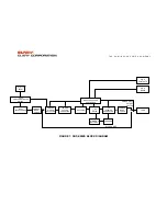
Page 4: ...owing exactly what patterns the supply utility power maintains and by knowing exactly the condition and life expectancy of the battery reserve Reference the block diagram for a simplified explanation...

Page 5: ...NE EMERGENCY CUTOFF SWITCH VOLTAGE WINDOW DETECTOR COMMON MODE CHOKE RECTIFIER CHARGER POWER FACTOR CORRECTOR DC RAILS MICROPROCESSOR CONTROLLER AC INVERTER GENERATOR LOAD STANDBY BATTERY COMMON MODE...

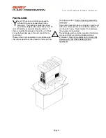
Page 6: ...it report this to your carrier These units are encapsulated in a protective wrap that comes apart once the product is removed from the shipping carton Save all packing material for future use Take ext...

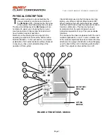
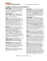
Page 7: ...nhanced to ensure you have a full understanding of the operation of this system Visual indicators used on the front panel are long lasting very efficient light emitting diodes LED When operating the p...

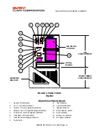
Page 8: ...rating indicator 11 Bypass indicator 4 Battery Level Charge discharge indicators 12 Alarm Silence switch 5 Load Level Output capacity indicators 13 Fault indicator 6 Cold Start DC start switch 14 Batt...

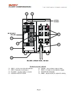
Page 9: ...IGNAL Open collector signal contacts 17 INPUT Dual pole circuit breaker 21 RS232 Computer communications signals 18 DC INPUT Auxiliary battery connector 22 IDENTIFICATION LABEL 19 SYSTEM OUTPUT 120VAC...

Page 10: ...l Rear Panel Callouts 16 INPUT Terminal Block 3 position 20 Signal Open collector signal contacts 17 INPUT BREAKER Dual pole circuit breaker 21 RS232 Computer communications signals 18 DC input Auxili...

Page 11: ...tility voltage is available it may still be a requirement to initialize some equipment When this switch is pressed in for at least two seconds the system will start up on battery power The SYSTEM ON O...

Page 12: ...o be stored it is recommended to refresh the internal battery at least once every 90 days To do this plug the system in position the power On Off switch to ON press and hold at least two seconds the L...

Page 13: ...nates An intermittent audible alarm will sound The SILENCE Switch may be operated at this time it must be held in for at least 2 seconds to quiet the alarm As battery discharge continues in this condi...

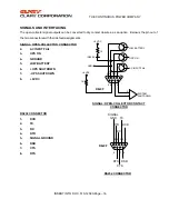
Page 14: ...OLLECTOR CONNECTOR 2 AC INPUT FAIL 3 UPS ON 4 GROUND 5 LOW BATTERY 6 UPS SHUTDOWN 7 UPS SHUTDOWN 8 9VDC RS232 CONNECTOR 1 DCD 2 TX 3 RX 4 DTR 5 SIGNAL GROUND 6 DSR 7 CTS 8 RTS SIGNAL OPEN COLLECTOR CO...

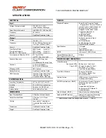
Page 15: ...ature Controlled Reversible Forced Air Dimensions See Model Selection Guide Weight See Model Selection Guide DESIGN Standard Features Power Factor Corrected Digital Regenerative On Line Sinewave Inver...

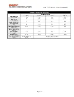
Page 16: ...s 1000 700 1250 875 1500 1050 2000 1400 Input Current Amps 120VAC 7 2 8 8 10 7 14 3 Output Current Amps 8 3 10 4 12 5 16 7 Input Plug Standard NEMA Type 5 15P 5 15P 5 15P 5 20P Battery Backup Time Min...

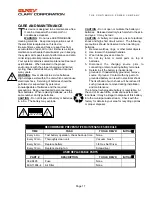
Page 17: ...lectrolyte is harmful to the skin and eyes It may be toxic CAUTION A battery can present a risk of electrical shock and high short circuit current The following precautions should be observed when wor...

Page 18: ...tory In consulting the factory always have the unit model number and serial number at hand This information is located on the identification label and is essential in retrieving your unit s performanc...

Page 19: ...ive carrier available or via customer s shipping instructions 2 3 The nature of certain equipment installations may be such that it would be impractical or technically infeasible to remove the Clary p...

Page 20: ...362 8908 Circuit Breaker 363 11043 AC Output Lamp 362 8495 Fuse 15 Amp 250VAC 171 9519 Handle 120 12535 2 Filter Assembly LEVEL II PART NO DESCRIPTION 360 9307 4 Output Terminal Block 4 Position 360 9...

Page 21: ...ff by the Load On Off switch on the Front panel The Internal Hard Bypass is protected by the Input Circuit Breaker See System Schematic 118 14052 WARNING Whenever UPS has utility power on the input an...

Reviews: