


T H E C O N T I N U O U S P O W E R C O M P A N Y
Page 4
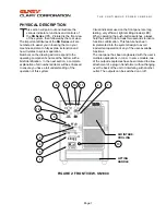
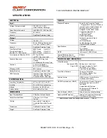
TECHNICAL DESCRIPTION
he SN Series
Continuous
Power System
(CPS) is a revolutionary new concept in total
power protection and management. The SN
Series is a microprocessor-based UPS that
now allows the user to set most of the control
feature parameters. By directly linking a personal
computer to the SN Series RS232 port, frequency
settings and operation, alarm signals, load
switching, fan operation, etc. can all be programmed
to meet specific application requirements.
The SN Series is a true on-line, continuous power
UPS. In the tradition of Clary products, the SN
Series generates the same high quality and proven
reliability to provide the best power protection
available for today’s critical applications.
In keeping with state-of-the-art design, the power
electronics are completely governed by an on-board
microprocessor. Given the powerful memory
capability of today’s microcontrollers, this
microprocessor has evolved the UPS into an all-in-
one complete power distribution and monitoring
center. Not only is your critical load insured of the
most reliable and constant power available, but the
user may now continuously track status of the
supply components that keep the entire system
operational. Production downtime can now be
virtually eliminated by knowing exactly what patterns
the supply utility power maintains and by knowing
exactly the condition and life expectancy of the
battery reserve.
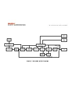
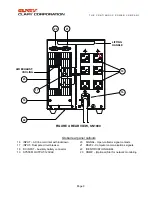
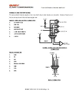
Reference the block diagram for a simplified
explanation of the system’s operation. The AC utility
source is connected to the power and micro-
electronics when the input switch is closed. The
input line is filtered, power factor corrected and
rectified for enhanced performance without
disturbing other equipment that may share the same
utility circuit. In
SN
units, an input isolation
transformer is added to accept a wide range of input
voltages for global applications. Output
transformers, SNMP adapters and many other
options are available.
The microprocessor controls an
Inverter Generator
that produces a low harmonic, AC sinewave for
continuous power applications.
When the input AC utility line fails, the battery circuit
within this system takes over to ensure continuous
power. Only after properly rated power is returned,
does the microprocessor reconnect the input source
back into the system.
The microprocessor is directly tied to an external
RS232 connector port. This allows the user to
monitor and even set some of the operating
parameters. With a simple link to a personal
computer using the SNConfig software program, you
can actually view, on your monitor, the event history
of the power distribution system with the
SN Series
unit as the central hub. More sophisticated users
may implement the optional SNMP package to
accomplish full
Network Power Management
.
T


