


17
16
19
18
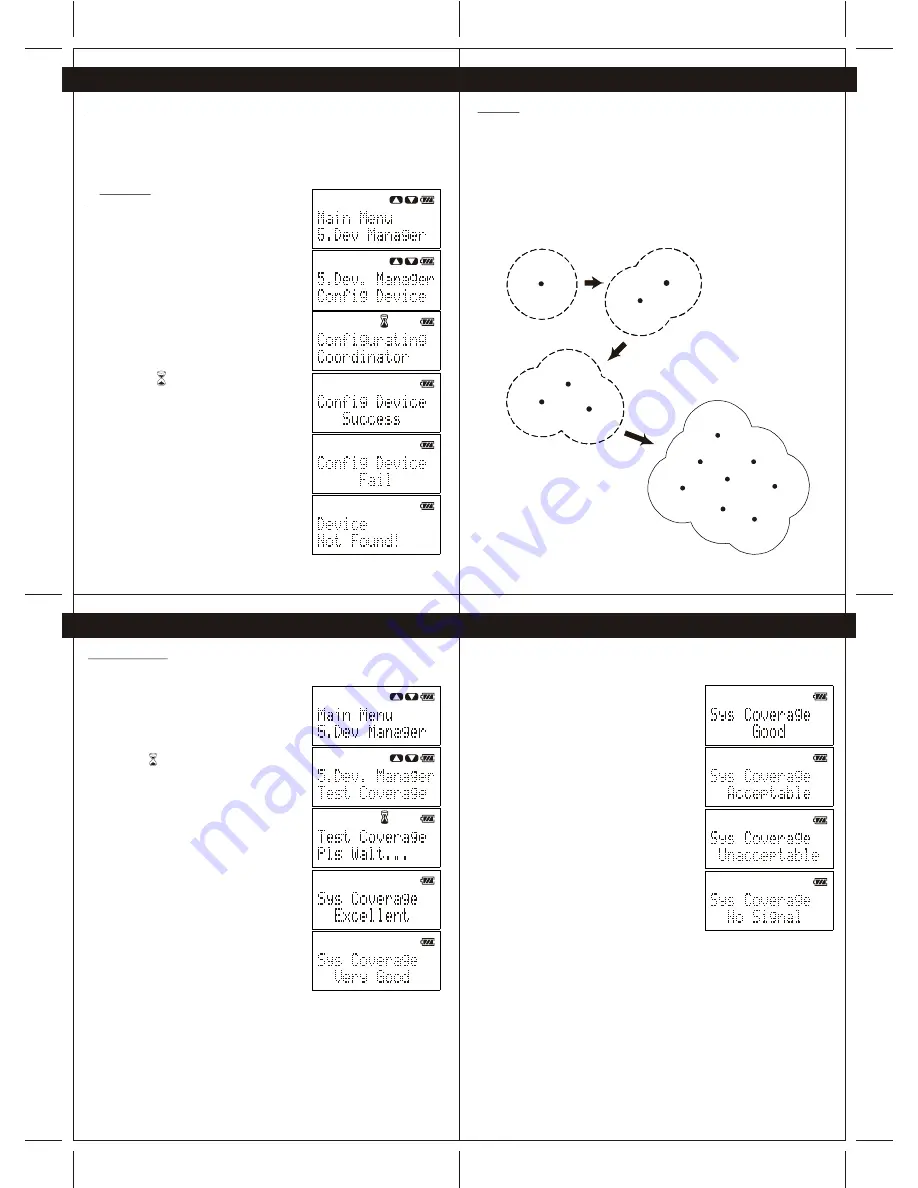
6. Device Configuration
This section provides information for user to link up their CG100 devices to form a
wireless network. The device configuration is fundamental process for wireless control of
each CG100 device. User is required to configure the Coordinator (CG100C) primarily
before configurating the other CG100 devices. Also, the system allows only ONE Coordinator
(CG100C) is configured in the network. The procedures to configure the coordinator and the
other CG100 devices are illustrated in following sections.
6.1 Coordinator
To configure the coordinator, perform the following
steps.
1 -Power up the Coordinator (CG100C) and Wireless
remote controller(CG100R).
2 -Connect the Wireless remote controller to the
Coordinator through the provided cable.
3 -Press the "Navigation" button of the Wireless
remote controller to enter Menu, and then scroll to
"Dev. Manager" of the Menu.
4 -Press "Yes" button to enter "Dev. Manager" Menu,
and then scroll to find "Config Device".
(Note: All the device in system need to re-configure
if the Coordinator is configured)
5 -Press "Yes" button to configure the Coordinator.
(Note: The icon is indicating that Wireless remote
controller is configuring the Coordinator)
(Note: The process to configure coordinator may
take a minute)
6 -When the coordinator is configured successfully,
the Wireless remote controller will show "Success".
During the configuration of Coordinator, if "Fail" or
"Device Not Found" is shown on the display,
please check the power of the Coordinator and the
connection between the Coordinator and Wireless
remote controller. Then perform step 1 to step 5 again.
6. Device Configuration
6.2 Device
When the Coordinator (CG100C) is configured successfully, user may configure other CG100
devices to establish network connection with the Coordinator. To achieve the best system
performance, user is strongly advised to test the system coverage of the location that is
planned to install the CG100 devices. On the other hand, when a CG100 device is configured
successfully, the system coverage will be increased by the newly added CG100 device
(Figure 6-1).
Therefore, user is strongly recommended to install and configure the CG100 devices which
are close to the Coordinator firstly for extending the system coverage for other CG100
devices which are far from the Coordinator. The procedures to test the system coverage and
to configure the CG100 devices are illustrated in Section 6.2.1 and Section 6.2.2.
Coord inator
Syst em
Cove rage
Coordi nator
System
Covera ge
New
Device
Coord inator
System
Coverage
Device
New
Device
Coordin ator
System
Coverag e
Device
New
Device
New
Device
New
Device
New
Device
New
Device
New
Device
Figure 6-1 newly added device will extend the coverage of system.
6. Device Configuration
6. Device Configuration
6.2.1 Test Converge
To test the system coverage before configurating a new device, perform following steps
1 -Place the Wireless remote controller (which is used to
configure the Coordinator before) to the location
which is planned to install the new device.
2 -Press the "Navigation" button to enter Menu, select
"Dev. Manager", and then go to "Test Coverage"
and press "Yes".
(Note: The icon is indicating the Wireless remote
controller is testing the network coverage.)
3 -After several second, the testing result will show
on the screen.
If the result is either Excellent, Very Good, Good or
Acceptable, user can install the new device to the
tested location. Otherwise, user may need to change
the installation location
After finding a correct location for device installation, user may install the new
CG100 device to such location and prepare to configure the new device.
Coordinator
System
Coverage
New
Device
Coordinator
System
Coverage
Device
Coordinator
New
Device
System
Coverage
New
Device
New
Device
New
Device
New
Device
New
Device
New
Device
Device
Coordinator


