45
44
10. Timer Function
11. N-Way Configuration
9. System Setting
10. Timer Function
46
47
9.5 Version
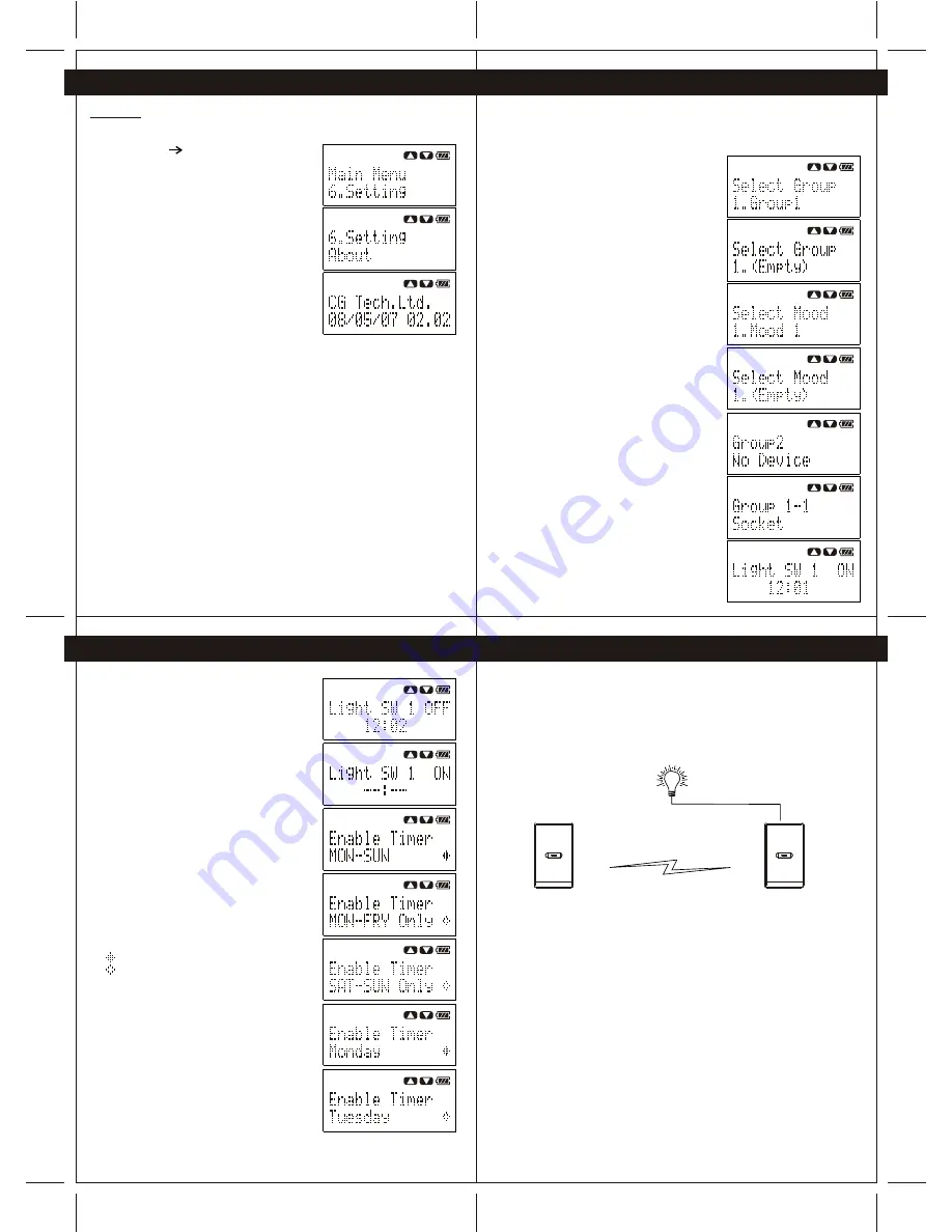
To view the firmware version of Wireless remote controller, perform following steps.
1- Press the "Navigation" button to enter Menu, then
select "Setting" "About"
2- Press "Yes" button to view the firmware verison.
User is able to configure the timer function of a device after the system clock is
configured. To configure the timer of the device, perform following steps.
Important: Please ensure the Wireless remote controller is within the system
coverage and the target device is operating before configuring the timer function.
1- Press the Navigation button to enter Menu, and
then select "Device Timer"/
(Note: All the groups and moods will show on
the screen, user may scroll to view the groups
and moods.)
(Note: If there is any device added to the
group/mood, the Wireless remote controller will
show the name of the group/mood.)
(Note: If there is no device added to the
group/mood, the Handheld with show
"(Empty)".)
2- Press "Yes" button to select the desired
group/mood.
(Note: if there is no device added to the group,
the Wireless remote controller will show "No
Device".)
(Note: If there is/are device(s) added to the
group, the Wireless remote controller will show
the name of the device.)
3- Press "Yes" button to select the device.
The Wireless remote controller will get the timer
setting of the selected device wirelessly.
4- After the timer setting of the device is obtained
successfully, the Wireless remote controller will
show the ON time, OFF time and weekly schedule
of the device.
When the timer setting is "--:--" . Which is
indicating such timer function of the device is
disabled. For example, when the timer setting
of a light switch is
"Light SW 1 ON --:--"
"Light SW 1 OFF 12:02"
Which means the ON timer of the light switch is
disabled and the light switch will only turn OFF
at 12:02.
5- Press "Yes" to set ON and OFF timer.
If the timer function is disabled, press up/down
button to enable the timer.
If user wants to disable the timer function,
press up/down to disable the timer.
After the ON/OFF timer is set, press "Yes" button
to send the new timer setting to the device.
6- User may also set the weekly schedule of the
timer
function:
MON-SUN
MON-FRY Only
SAT&SUN Only
Monday
Tuesday
Wednesday
Thursday
Friday
Saturday
Sunday
Press "Yes" button to enable or disable the
weekly schedule
During setting the weekly schedule:
- Enabled
- Disabled
N-Way function is a special feature of the CG100 devices. Through the N-Way
configuration, user may use a CG100 device to control the load of another CG100
device wirelessly.
For example, when there is a wall light installed in the corridor and user is desired to
control the wall light at both end of the corridor. User may install two one-gang
switches to both end of the corridor and the wall light may connect to only
one of the switch (Switch B) (see Figure 11-1).
User may configure the switch A as a N-Way Controller and Switch B as a N-Way
Device. After N-Way configuration, user can use the control button on both
Switch A and Switch B to control the same light.
Note:
When the device is a N-Way Controller, user cannot re-configure the device as a
N-Way Device before removing the N-Way function of the device.
When the device is a N-Way Device, the user cannot re-configure the device as a
N-Way Controller before removing the N-Way function of the device.
To remove the N-Way function of the device, please refer to Section 11.2..
Wireless Control
Switch A
N-Way
Controller
Switch B
N-Way
Device


