Chapter 1
Outline
4
1
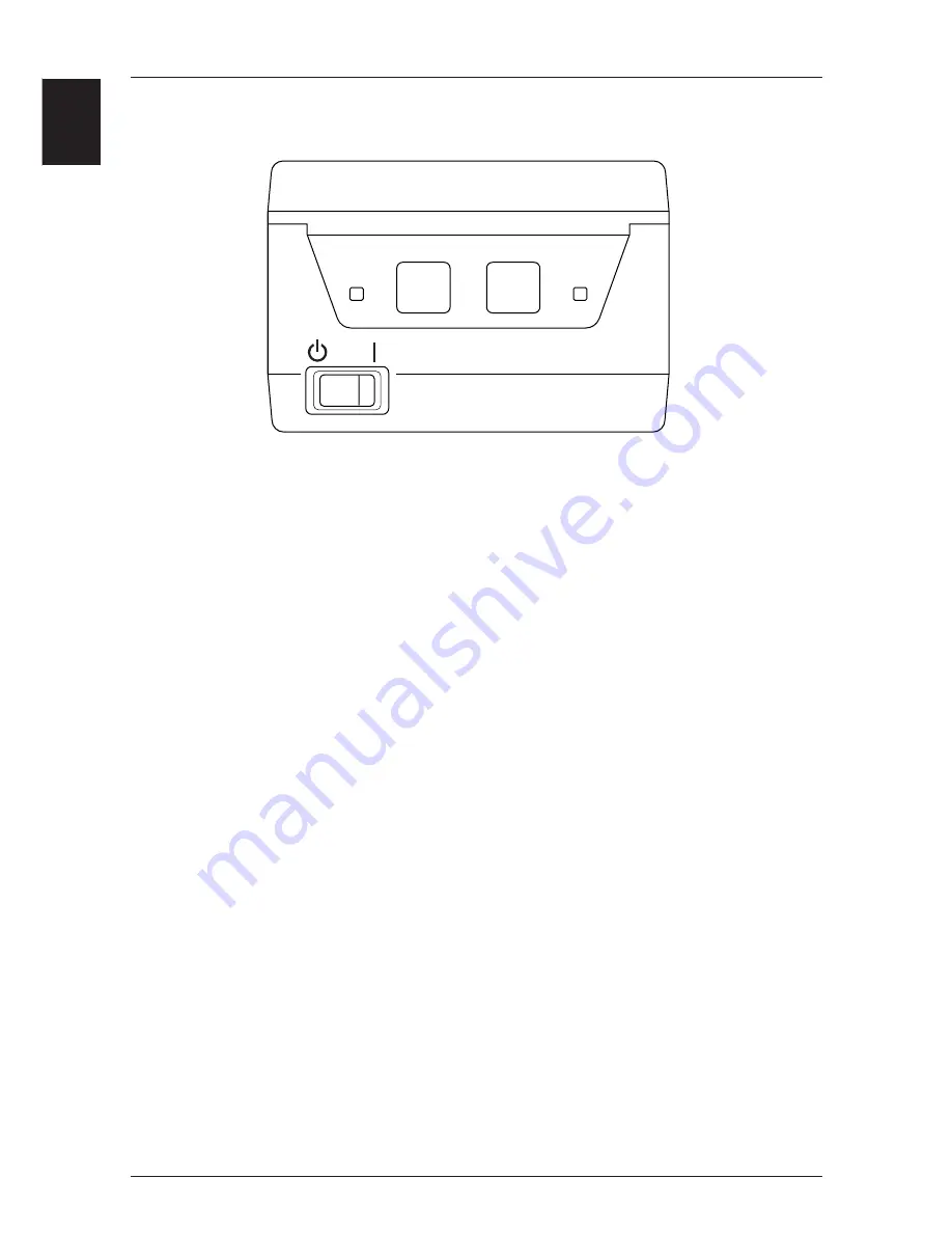
Operation Panel
1
POWER Indicator (Green)
Lights up when the power switch is turned on and power is being supplied to the
printer.
2
RECEIPT Key
Feeds receipt paper. Pressing once causes the paper to advance one line, based on the
amount for a carriage return set previously. If the key is pressed continuously, the
paper is fed continuously.
3
JOURNAL Key
Feeds journal paper. Pressing once causes the paper to advance one line, based on the
amount for a carriage return set previously. If the key is pressed continuously, the
paper is fed continuously.
4
ERROR Indicator (Orange)
Lights up or blinks when an error occurs. The content of the error is indicated by the
indicator lighting up or blinking (see “Chapter 5 - Sensors and Error Indications,” on
page 30). Goes off when the printer's condition returns to normal.
•
When the RECEIPT key and JOURNAL key are pressed separately, or are pressed
together when the power is switched on, it is possible to enter the test printing and
the printer internal setting mode (see “Chapter 4 - Using the Printer,” on pages
21~24).
3
2
1
4
Summary of Contents for CBM-262 Type II
Page 1: ...User sManual LINE THERMAL PRINTER CBM 262 MODEL ...
Page 41: ...6 31 Chapter 6 Interfaces Serial Interface Parallel Interface Drawer Kick Connector ...
Page 53: ...6 43 Drive Circuit 1 2 3 4 5 6 1 5A 24V Drawer Kick Connector ...
Page 54: ...6 Chapter 6 Interfaces 44 ...
Page 55: ...7 45 Chapter 7 Print Control Codes List of Control Codes Input Data Format ...
Page 116: ...7 Chapter 7 Print Control Codes 106 ...
Page 118: ...8 Chapter 8 Character Code Tables 108 Code Page ...
Page 119: ...8 109 Code Page ...
Page 120: ...8 Chapter 8 Character Code Tables 110 ...
Page 121: ...8 111 Japanese Code Table Japanese Code Table ...
Page 130: ...9 Chapter 9 Appendix 120 External View 12 359 162 ...


