3-7
Cisco uBR924 Router Hardware Installation Guide
OL-0338-01 (3/2000)
Chapter 3
Installing the Cisco uBR924 Router
Connecting to Telephones or Fax Devices
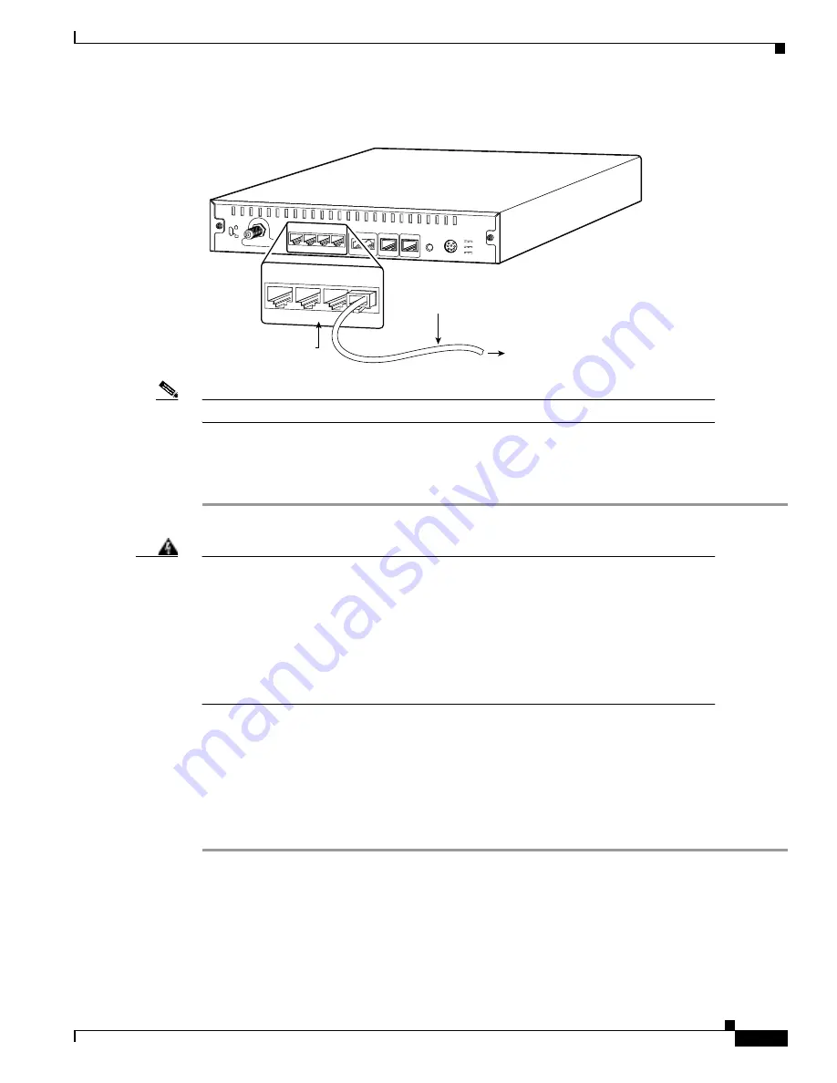
Figure 3-2
Connecting the Ethernet Cable to the Cisco uBR924 Cable Access Router
Note
Do not connect the Ethernet cables into the RJ-45 console connector.
Step 3
Press the cable end firmly into the router’s Ethernet receptacle and connect the other end to the
computer or hub as applicable.
Step 4
Repeat steps 2 and 3 for each Ethernet connection from the Cisco uBR924 cable access router.
Warning
To avoid electric shock, do not connect safety extra-low voltage (SELV) circuits to the
telephone-network voltage (TNV) circuits. LAN ports contain SELV circuits and WAN
ports contain TNV circuits. RJ-45 connectors are used for both LAN and WAN
ports—use caution when connecting cables to ensure that the proper ports are being
connected.
Hazardous network voltages are presented in WAN ports regardless of whether power
to the unit is OFF or ON. To avoid electric shock, use caution when working near WAN
ports. When detaching cables, detach the end away from the unit first.
Connecting to Telephones or Fax Devices
If you have purchased voice services from your service provider and are using a Cisco IOS image with
voice support, use the following procedure to connect the Cisco uBR924 router to telephone or fax
devices at the site:
Step 1
Use one RJ-11 to RJ-11 cable for each analog telephone or fax device that is directly connected to the
Cisco uBR924 router. If multiple analog telephones or fax devices are to be connected to a VoIP
telephone line, ensure the wiring is in place to support the configuration and assemble all needed items
to support the site’s configuration.
Cable TV In
Power
Reset
Console
Line
Phone
v1+v2 v2
X
Ethernet 0
X
X
X
1
2
3
4
5V
3A
8V
0.65A
40V
7mA
Cisco uBR924
To computer
17649
X
Ethernet 0
X
X
X
1
2
3
4
Ethernet 10BaseT
(RJ-45)
Ethernet cable


