3-5
Cisco uBR924 Router Hardware Installation Guide
OL-0338-01 (3/2000)
Chapter 3
Installing the Cisco uBR924 Router
Connecting to the Cable System
•
Do not work on the system or connect or disconnect any cables (Ethernet, cable, or power) during
periods of lightning activity—the possibility of serious physical injury exists if lightning should
strike and travel through those cables. In addition, the equipment could be damaged by the higher
levels of static electricity present in the atmosphere.
Note
Adhere to the safety guidelines presented in the “Safety” section on page 2-1 before
following procedures in the remainder of this chapter. Be sure all equipment to be
connected to the cable access router is powered off.
Caution
Do not connect the router to power at this point because the router will begin its initial
power-on sequence and attempt to connect to the network. The unit should be powered on
only after all other connections have been made, as described later in this chapter.
Connecting to the Cable System
To connect the Cisco uBR924 router to the cable system:
Step 1
Verify that the router is not connected to power.
Step 2
Locate the RF coaxial cable coming from the CATV wall outlet.
Step 3
Install a cable splitter/directional coupler if needed to separate signals for TV and computer usage. If
necessary, also install a high-pass filter to prevent interference between the TV and computer signals.
Step 4
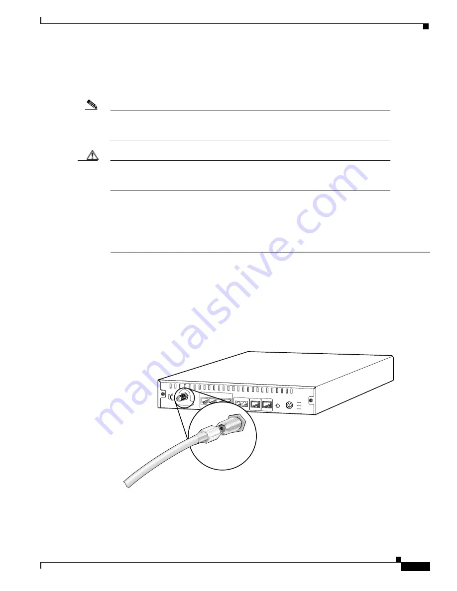
Connect the RF coaxial cable to the router’s F-connector. Hand-tighten the connector, making sure it is
finger tight; then give it a 1/6 turn with a wrench. (See Figure 3-1.)
Figure 3-1
Connecting the CATV Coaxial Cable to the Cisco uBR924 Router
To cable source
17648
Cable TV In
Power
Reset
Console
Line
Phone
v1
v2
X
Ethernet 0
X
X
X
1
2
3
4
5V
3A
8V
0.65A
40V
7mA
Cisco uBR924
F connector
(Cable TV In)


