8-29
Cisco ASR 1000 Series Aggregation Services Routers Hardware Installation Guide
OL-13208-09
Chapter 8 Cisco ASR 1002 Router Overview and Installation
Connecting the Console and Auxiliary Port Cables
Connecting the Console and Auxiliary Port Cables
This section describes how to attach a cable to the Cisco embedded ASR1000-RP1 console or auxiliary
ports on the Cisco ASR 1002 Router. The Cisco ASR 1002 Router uses RJ-45 ports for both the auxiliary
port and console port to attach a modem or console terminal.
Caution
Both the console and the auxiliary ports are asynchronous serial ports; any devices connected to these
ports must be capable of asynchronous transmission. (Asynchronous is the most common type of serial
device; for example, most modems are asynchronous devices.) To meet Class A emissions requirements,
shielded cables must be used for the console and auxiliary port connectors.
Before you can use the console interface on the router using a terminal or PC, you must perform the
following steps:
Step 1
Before connecting a terminal to the console port, configure the terminal to match the chassis console
port as follows: 9600 baud, 8 data bits, no parity, 1 stop bits (9600 8N1).
Step 2
Connect to the port using the RJ-45 to DB-9 cable.
Note
For information about how to change the default settings to meet the requirements of your terminal or
host, see
Cisco IOS Terminal Services Configuration Guide
.
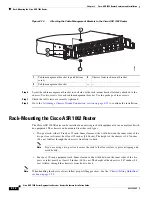
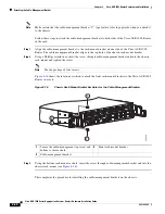
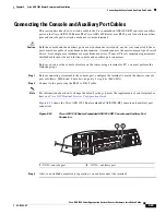
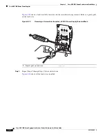
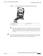
Figure 8-20
shows the Cisco ASR 1002 Router embedded ASR1000-RP1 console and auxiliary port
connectors.
Figure 8-20
Cisco ASR 1002 Router Embedded ASR1000-RP1 Console and Auxiliary Port
Connectors
Step 3
After you establish normal router operation, you can disconnect the terminal.
280285
ASR 1002
stat
pwr
min
maj
crit
0
1
C
/A
A
/L
0
1
C/
A
A/
L
STAT
QE0
QE1
QE2
QE3
BOOT
CARRIE
R
LINK
PWR ST
AT
MTS
MGMT
AUX
CON
SPA-4XOC
3-POS
S
T
AT
U
S
0
1
2
3
C
/A
A
/L
C
/A
A
/L
C/A
A
/L
C
/A
A
/L
1
2
1
CON—console port
2
AUX —auxiliary port

