

ciscoBus Token Ring Card and Applique Installation and Upgrade Instructions 25
Installation
Finishing the Installation
The following steps describe the final installation procedure:
Step 1
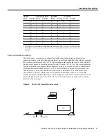
Connect the external cables from your Token Ring network to the Token Ring connectors
on the appliques.
Step 2
If necessary, reconnect other cables on the rear of the chassis.
Step 3
Replace the chassis cover, but do not secure it with the cover screws until you have verified
successful installation.
Caution
You must replace the chassis cover before powering up the system for an installation
check. However, you do not need to tighten the screws.
Step 4
Proceed to the next section to check the installation before configuring the interface.
Checking the Installation
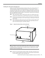
After you have installed a CSC-C2CTR and/or APP-LTR2, verify the installation before you replace
the front panel by observing the LEDs on the system processor card, the CSC-CCTL2 ciscoBus
controller card, the CSC-C2CTR card, and the APP-LTR2 in the rear of the chassis. The LEDs on
the CSC-C2CTR will not light until the new interfaces are configured and brought up. After you
configure the interfaces (as described in the section “Configuring the Interfaces” on page 29), you
will check the CSC-C2CTR LEDs and use the show EXEC commands to verify the interfaces.
Warning
Never power up the system when the top cover is removed because the power supply and
dangerous voltages are exposed. Also, the internal airflow is misdirected when the cover is off,
which can cause the system to overheat and subsequently shut down.
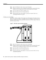
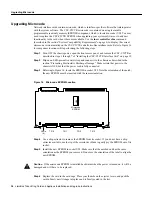
LED Functions
The LEDs on the CSC/3 and CSC/4 processor cards indicate the status of the system software. If the
system detects a problem at startup, the system error LED on the processor card will be on or will
flash. The CSC-CCTL2 LEDs verify the presence (correct installation) of all cards installed in the
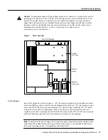
ciscoBus. Also, on the APP-LTR2 (see Figure 4), a single, green, power LED goes on to indicate
that the applique is receiving power from the CSC-C2CTR. After the interfaces are configured and
brought up, the LEDs on the CSC-C2CTR go on for each active port. (See the section “CSC-C2CTR
Interface Card” on page 4.)
Processor Card LEDs
Either a CSC/3 or a CSC/4 can be installed in your system. Both have three LEDs with similar
functions. When viewing either card when it is installed in the system card cage, the right LED is
the system OK light, which goes on to indicate that the system is operating correctly. The far left
LED on both is a system error LED, which goes on or flashes if the system detects an error during
startup or is unable to start up the operating system.
The three CSC/4 LEDs are shown in Figure 13. The left yellow status LED goes on momentarily
during initialization, flashes if there is an error, and is off under normal conditions. The middle,
yellow LED is not used. The right, green, OK LED goes on at startup and remains on to indicate that
the system software has booted and is operational.