3-3
Cisco TelePresence System
OL-16441-01
Chapter 3 Options for the Cisco TelePresence System 1000
Auxiliary Control Unit
Step 3
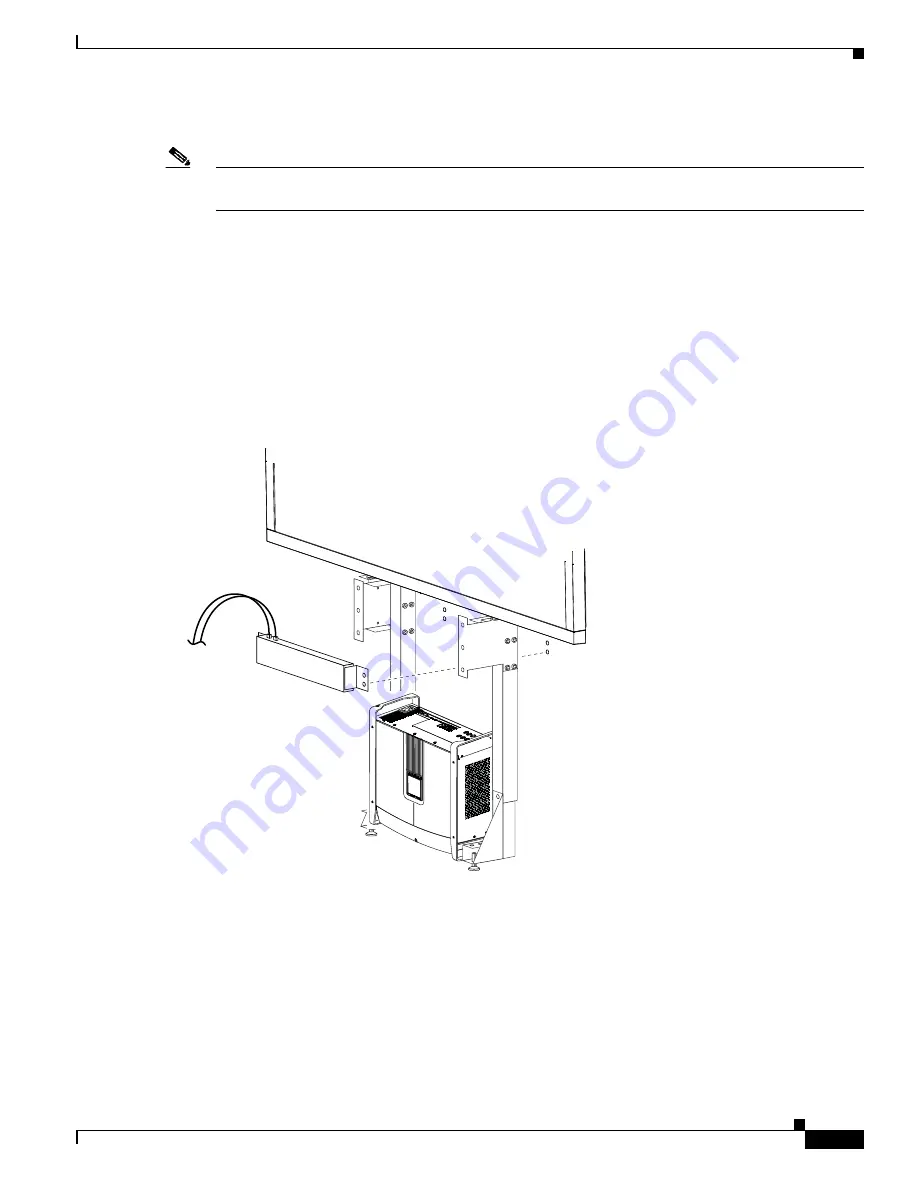
Attach the auxiliary control unit to its bracket using the supplied 5 mm screws.
Note
Attach the bracket so that the shortest part of the bracket attaches to the wall; otherwise the unit is too
wide to fit between the display supports.
Step 4
If your installation uses a presentation codec, connect the Ethernet cable to the auxiliary control unit as
follows:
•
Connect the Primary Codec Document Camera Ethernet connection (orange Ethernet connection on
the primary codec) to one Ethernet port of the auxiliary control unit.
•
Connect the other Ethernet port of the auxiliary control unit to the Presentation Codec Ethernet port
(white/red Ethernet connection on the presentation codec).
Step 5
Measure and drill the wall mounting holes for the auxiliary control unit. Hold the unit against the wall
and use it as a template for the mounting holes.
Figure 3-2
Measuring and Drilling Holes for Auxiliary Control Unit
204197
Ethernet
c
ab
le
s


