DS726PP2
27
CS4525
6.1.1.2
Crystal Oscillator Mode
To use an external crystal in conjunction with the internal crystal driver, a 20 pF fundamental mode par-
allel resonant crystal must be connected between the XTI and XTO pins. This crystal must oscillate within
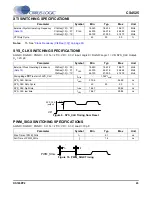
the frequency ranges specified in the XTI switching specifications table on
. Nothing other than
the crystal and its load capacitors should be connected to XTI and XTO. The SYS_CLK pin should be
connected to ground through a 22 k
Ω
pull-down resistor to prevent the CS4525 from recognizing system
noise on the SYS_CLK pin as a valid clocking signal.
In this mode, the CS4525 will automatically drive the generated internal clock out of the SYS_CLK pin.
This can be disabled with the EnSysClk bit which will cause the SYS_CLK pin to become high-impedance.
Also, the DivSysClk bit allows the frequency of the generated internal clock to be divided by 2 prior to be-
ing driven out of the SYS_CLK.
It should be noted that the internal oscillator driver is disabled when the CS4525 is in reset (RST is low).
Any external devices connected to the SYS_CLK output will not receive a clock signal until the CS4525
is taken out of reset.
If an external crystal is connected to the XTI/XTO pins while an input clock signal is present on the
SYS_CLK pin following the release of RST, then the CS4525 will automatically use the SYS_CLK pin for
its internal clock. Refer to
for a details about this mode of operation.
below demonstrates a typical clocking configuration using the crystal oscillator.
Referenced Control
Register Location
EnSysClk.............................
“SYS_CLK Output Enable (EnSysClk)” on page 69
DivSysClk............................
“SYS_CLK Output Divider (DivSysClk)” on page 69
DSP
RST
RST
Reset
SYS_CLK
Clock_In
XTI
XTO
Figure 13. Typical Crystal Oscillator Clocking Configuration
CS4525

