74
DS632F1
CS44800
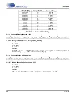
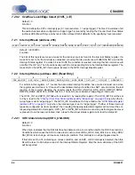
7.32.2
Power Supply Rejection Reset (PSR_RESET)
Default = 0
0 - force reset condition
1 - remove reset condition
Function:
This bit is used to assert a reset condition to the on-card PSR components. When set to a ‘0’b, the
PSR_RESET signal will be asserted low. The reset condition will continue as long as this bit is set to a
‘0’b. This bit must be set to a ‘1’b for proper PSR operation.
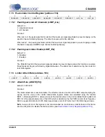
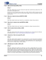
7.32.3
Power Supply Rejection Feedback Enable (FEEDBACK_EN)
Default = 0
0 - disable
1 - enable
Function:
Enables the internal power supply rejection feedback logic.
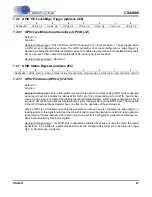
7.32.4
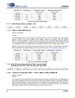
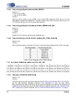
Power Supply Sync Clock Divider Settings (PS_SYNC_DIV[2:0])
Default = 000
Function:
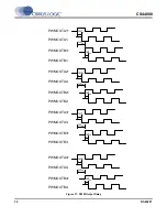
These three bits determine the divider for the XTAL clock signal for generating the PS_SYNC clock signal.
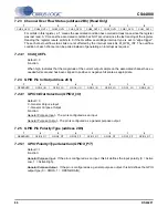
7.33
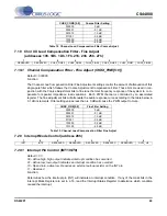
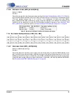
Decimator Shift/Scale (addresses 35h, 36h, 37h)
7.33.1
Decimator Shift (DEC_SHIFT[2:0])
Default = 010
Function:
These bits are used to scale the power supply reading (
Decimator Outd (addresses 3Bh, 3Ch, 3Dh)
) dur-
ing the PSR feedback calibration sequence. The combination of shift and scale factors
(DEC_SCALE[18:0]*2^(DEC_SHIFT[2:0])) can be viewed as a floating point coefficient. The floating point
coefficient will be determined during the PSR feedback calibration sequence. See
Decimator Scale
(DEC_SCALE[18:0])
register description and
“Recommended PSR Calibration Sequence” on page 44
.
PS_SYNC_DIV[2:0]
PS_SYNC Clock Divider
000
Output Disabled
001
Divide by 32
010
Divide by 64
011
Divide by 128
100
Divide by 256
101
Divide by 512
110
Divide by 1024
Table 17. Power Supply Sync Clock Divider Settings
7
6
5
4
3
2
1
0
RESERVED
DEC_SHIFT2
DEC_SHIFT1
DEC_SHIFT0
RESERVED
DEC_SCALE18 DEC_SCALE17 DEC_SCALE16
7
6
5
4
3
2
1
0
DEC_SCALE15 DEC_SCALE14 DEC_SCALE13 DEC_SCALE12 DEC_SCALE11 DEC_SCALE10 DEC_SCALE09 DEC_SCALE08
7
6
5
4
3
2
1
0
DEC_SCALE07 DEC_SCALE06 DEC_SCALE05 DEC_SCALE04 DEC_SCALE03 DEC_SCALE02 DEC_SCALE01 DEC_SCALE00

