16
RGU-100B
Instruction Manual
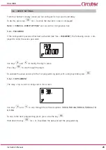
3�7�- INSTALLATION CONNECTIONS
All active conductors that supply the loads or part of the installation where protection is required must
pass through the associated
WGB
transformers.
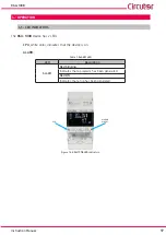
Connect the
WGB
transformer to the
RGU-100B
WGB
RGU-100B
RJ45
Channel 1
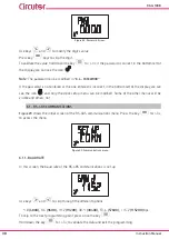
Figure 12: RGU-100B - WGB connection�
Note:
If a RJ45 connection cable other than the one supplied with the
WGB
is used, it must have a
cross-section of 4 x 2 x AWG24/7. The cable must be a maximum length of 9 metres.
Connect the output relay of the
RGU-100B�
If the installation is modified and it involves new transformer, a replacement of the
WGB
, the
RGU-
100B
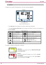
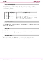
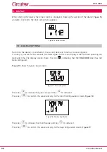
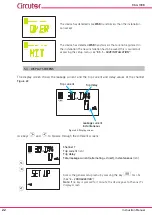
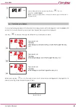
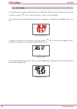
will detect this change and light the screens in yellow, see
"5�2�- PROBLEMS OR CHANGES IN THE
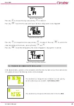
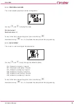
Figure 13: Change in the installation�
Summary of Contents for RGU-100B
Page 1: ...INSTRUCTION MANUAL Protection and monitoring relay RGU 100B M256B01 03 20A...
Page 2: ...2 RGU 100B Instruction Manual...
Page 47: ...47 Instruction Manual RGU 100B 11 CE CERTIFICATE...
Page 48: ...48 RGU 100B Instruction Manual...
Page 49: ...49 Instruction Manual RGU 100B...
Page 53: ...53 Instruction Manual RGU 100B...


