10
RGU-100B
Instruction Manual
3�2�- INSTALLATION
When the device is on, its terminals, opening covers or removing elements may ex-
pose the user to parts that are hazardous to touch. Do not use the device until it is
fully installed.
The device must be installed inside a medium or low voltage electric panel or enclosure, with DIN rail
mounting (IEC 60715).
The device has a LED (
CPU
) that indicates voltage presence. Even in the case that the
aforesaid LED is off, the user still needs to check the device is disconnected from any
power supply.
The device must be connected to a power circuit protected by a fuse according to its power and con-
sumption rating. It must be fitted with a circuit-breaker or equivalent device to disconnect the device
from the power supply.
3�3�- PANEL ADAPTER 72 x 72 mm
Note:
The 72 x 72 mm panel adapter is a separately sold accessory.
CIRCUTOR
has a panel adapter for
RGU-100B
devices so that it can be installed on 72 x 72 mm panels.
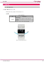
Figure 1
illustrates how the panel adapter is connected to an
RGU-100B
.
Before installing the adapter, the device must be disconnected from all power and
measurement supplies.
Figure 1: Installation of the panel adapter�
Table 3: Technical characteristics of the Panel Adapter�
Technical Specifications
Protection degree
IP40
Enclosure
Self-extinguishing V0 plastic
Summary of Contents for RGU-100B
Page 1: ...INSTRUCTION MANUAL Protection and monitoring relay RGU 100B M256B01 03 20A...
Page 2: ...2 RGU 100B Instruction Manual...
Page 47: ...47 Instruction Manual RGU 100B 11 CE CERTIFICATE...
Page 48: ...48 RGU 100B Instruction Manual...
Page 49: ...49 Instruction Manual RGU 100B...
Page 53: ...53 Instruction Manual RGU 100B...


