18
RGU-100B
Instruction Manual
4�2�- DISPLAY
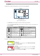
The device has a backlit LCD display that is split into two areas (
):
Data area
Unit and status areas
Figure 15: RGU-100B display areas�
The
data area
, which displays all the values measured by the device.
The
unit and device status area,
which displays the different statuses, units and device in-
formation (
).
Table 8: Display icons�
Icon
Description
Icon
Description
Alternating current
Prealarm activated
Direct current
The device clock has not been set up
Channel:
CH1
channel 1
A trip has been generated
Programming screen
Programming menu:
Locked with a password.
Unlocked.
Internal device error, contact
SAT
The device's display can change color, indicating:
Yellow color:
The installation has changed, see
Red color:
The relay has tripped due to leakage current, see
An Individual test has been carried out, see
An error was detected in the
WGB�
Summary of Contents for RGU-100B
Page 1: ...INSTRUCTION MANUAL Protection and monitoring relay RGU 100B M256B01 03 20A...
Page 2: ...2 RGU 100B Instruction Manual...
Page 47: ...47 Instruction Manual RGU 100B 11 CE CERTIFICATE...
Page 48: ...48 RGU 100B Instruction Manual...
Page 49: ...49 Instruction Manual RGU 100B...
Page 53: ...53 Instruction Manual RGU 100B...


