18
Carrying out measurements
6.2 Voltage Test
• Connect both test probes with UUT.
• As from a voltage of >12V the voltage tester switches on
automatically.
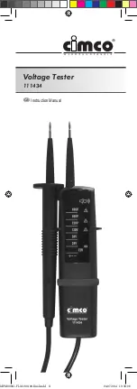
The voltage is displayed via LEDs (3).
For AC voltages the + and the – LED are illuminated
and an additional signal sound is audible.
For DC voltages the + or the – LED are illuminated
and an additional signal sound is audible.
The instrument is equipped with an LED row compris-
ing: 12, 24, 50, 120, 230, 400 and 690V.
For DC voltage, the polarity of the voltage displayed
refers to the instrument test probe (+).
6.3 Single-Pole Phase Test
• the single-pole phase test starts at an AC voltage of
approx. 100 V (pole > 100 V AC).
• When using single-pole phase tests to determine external
conductors the display function may be impaired under
certain conditions (e.g. for insulated locations).
The single-pole phase testing is not appropiated to
determine wheter a line is live or not. For this pur-
pose, the double-pole voltage test is always required.
• Connect instrument test probe to UUT.
A signal sound indicates the phase and the LED (4) is
illuminated in the display.
6.4 Continuity Test
Make sure that UUT is not live.
Test voltage polarity at handle test probe is positive
(+).
• Check that UUT is not live by carrying out a double-pole
voltage test.
• Connect both test probes with UUT.
A signal is audible for continuity and the LED for
continuity (5) is illuminated.
7.0 Maintenance
When using the instrument in compliance with the instruction
manual, no special maintenance is required. Should opera-
tional problems occur during daily use, our consulting service
will be at your disposal, free of charge.
If functional errors occur after expiration of warranty, our after
sales service will repair your instrument without delay.
MPM00061-FLM-000-00-final.indd 18
04.07.2014 10:38:09

