


8-2
Manual No 0-5072
weldskill 250, 350 service
December , 2008
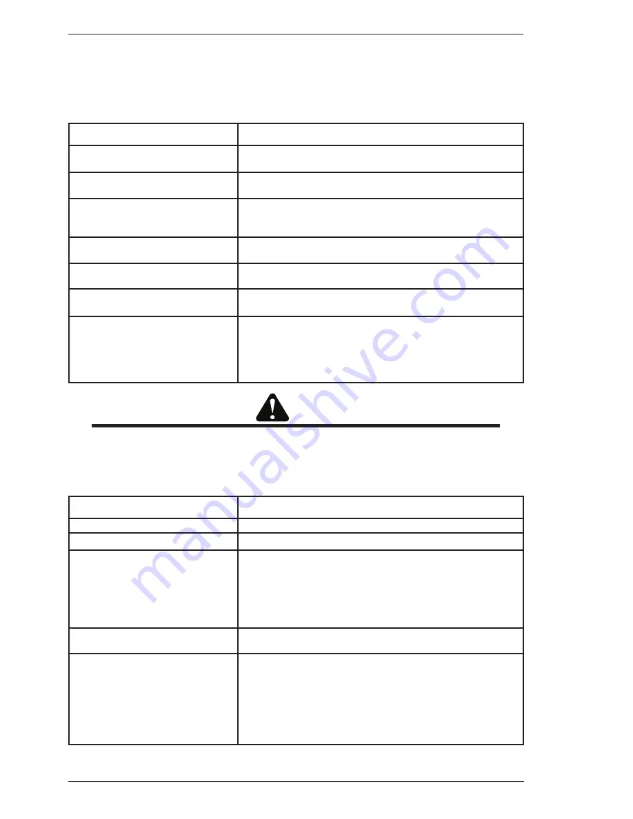
8.05 Solving Problems Beyond the Welding Terminals - Porosity
When there is a gas problem the result is usually porosity within the weld metal. Porosity always stems
from some contaminant within the molten weld pool which is in the process of escaping during solidification
of the molten metal. Contaminants range from no gas around the welding arc to dirt on the work piece
surface. Porosity can be reduced by checking the following points.
FAULT
CAUSE
Gas cylinder contents and flow
meter.
Ensure that the gas cylinder is not empty and the flow meter is
correctly adjusted to 5 litres per minute.
2 Gas leaks.
Check for gas leaks between the regulator/cylinder connection
and in the gas hose to the Power Source.
3 Internal gas hose in the Power
Source.
Ensure the hose from the solenoid valve to the torch adaptor
has not fractured and that it is connected to the torch adaptor.
4 Welding in a windy environment.
Shield the weld area from the wind or increase the gas flow.
5 Welding dirty, oily, painted, oxidised
or greasy plate.
Clean contaminates off the work piece.
6 Distance between the MIG torch
nozzle and the work piece.
Keep the distance between the MIG torch nozzle and the work
piece to a minimum.
7 Maintain the MIG torch in good
working order.
A
B
C
Ensure that the gas holes are not blocked and gas is exiting
out of the torch nozzle.
Do not restrict gas flow by allowing spatter to build up inside
the torch nozzle.
Check that the MIG torch O-rings are not damaged.
CAUTION
Disengage the drive roll when testing for gas flow by ear.
8.06 Solving Problems Beyond the Welding Terminals – Inconsistent Wire Feed
Wire feeding problems can be reduced by checking the following points.
FAULT
CAUSE
Wire spool brake is too tight
Feed roller driven by motor in the cabinet will slip.
2 Wire spool brake is too loose
Wire spool can unwind and tangle.
3 Worn or incorrect feed roller size
A
B
C
Use ‘U’ groove drive feed roller matched to the aluminium wire
size you are welding.
Use ‘V’ groove drive feed roller matched to the hard wire size
you are welding.
Use ‘knurled V’ groove drive feed roller matched to the flux
cored wire size you are welding.
4 Mis-alignment
of
inlet/outlet
guides
Wire will rub against the mis-aligned guides and reduces wire
feedability.
5 Liner blocked with swarf
A
B
C
Increased amounts of swarf are produced by the wire passing
through the feed roller when excessive pressure is applied to
the pressure roller adjuster.
Swarf can also be produced by the wire passing through an
incorrect feed roller groove shape or size.
Swarf is fed into the conduit liner where it accumulates thus
reducing wire feedability.
Summary of Contents for WeldSkill 250 MIG
Page 6: ......
Page 12: ...1 December 1 2008 weldskill 250 350 Manual No 0 5072 This page left intentionally blank...
Page 20: ...2 Manual No 0 5072 weldskill 250 350 December 1 2008 This page left intentionally blank...
Page 24: ...3 Manual No 0 5072 weldskill 250 350 December 1 2008 This page left intentionally blank...
Page 28: ...4 Manual No 0 5072 December 1 2008 weldskill 250 350 This page left intentionally blank...
Page 36: ...6 Manual No 0 5072 weldskill 250 350 December 1 2008 This page left intentionally blank...
Page 44: ...8 Manual No 0 5072 weldskill 250 350 December 1 2008 This page left intentionally blank...
Page 50: ......