


SERVICE MANUAL
TRANSTIG 200 Pi
March 31, 2008
4-1
A
r
t # A-08343
180
410
1
2
3
4
5
6
7
8
360
15
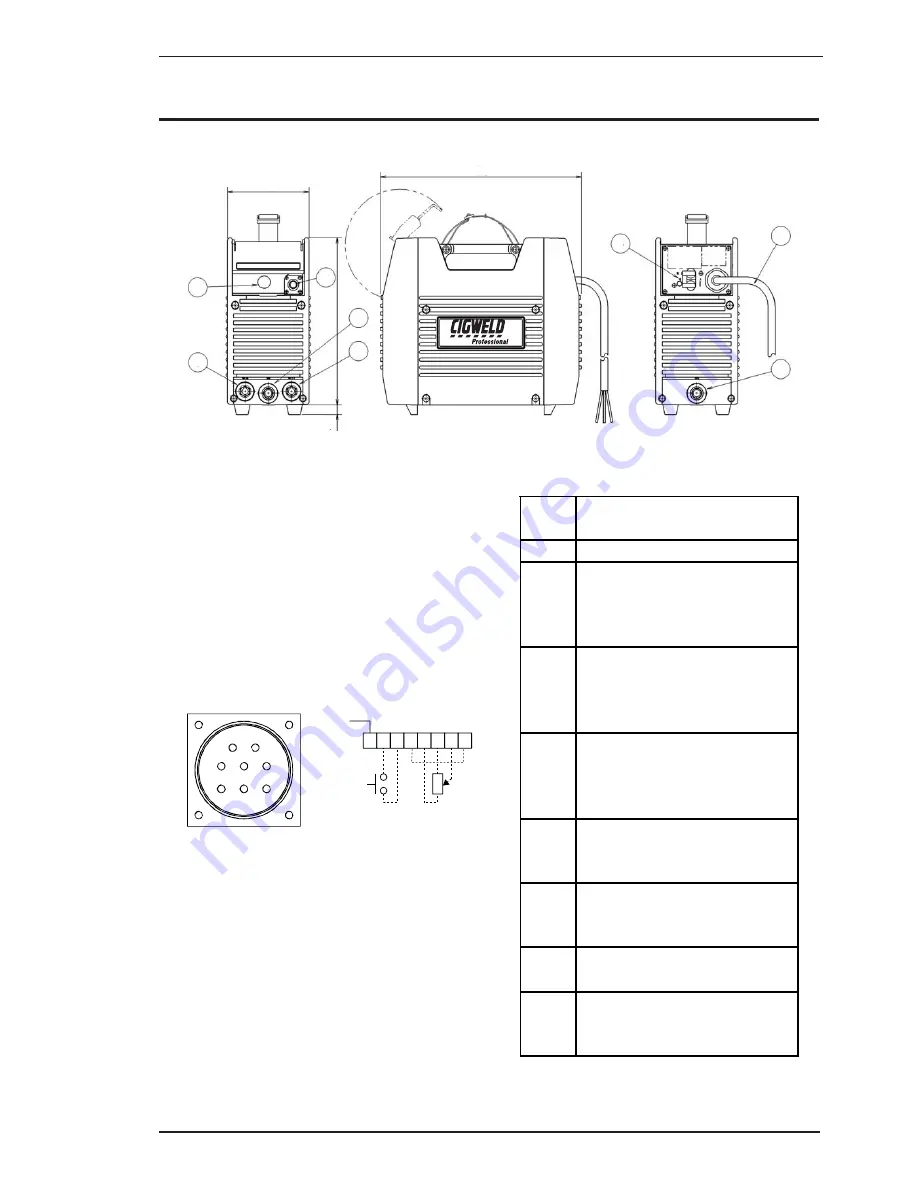
Figure 4-1: Transtig 200 Pi Power Source
SECTION 4:
OPERATION
4.01 Transtig 200 Pi Controls
1. Control Knob:
This control sets the selected weld
parameter, rotating it clockwise increases the
parameter and is indicated on the digital meter.
Pushing the knob inward displays the actual
welding voltage.
2. Remote Control Socket:
The 8 pin Remote Control
Socket is used to connect remote current control
devices to the welding Power Source. To make
connections, align keyway, insert plug, and rotate
threaded collar fully clockwise.
2
1
5
4
3
8
7
6
F
r
o
n
t View of 8-
S
ocket Receptacle
1 2 3 4 5 6 7 8
Gnd.
5k Ohms
A
r
t # A-08344
Figure 4-2: Front view of 8-Socket Receptacle
3. Positive Terminal:
Welding current flows from
the Power Source via heavy duty Dinse type
terminal. It is essential, however, that the male
plug is inserted and turned securely to achieve a
sound electrical connection.
4. Negative Terminal:
Welding current flows from
the Power Source via heavy duty Dinse type
terminal. It is essential, however, that the male
plug is inserted and turned securely to achieve a
sound electrical connection.
Socket
Pin
Function
1
Earth (Ground)
2
Torch Switch Input (24V) to
energize weld current. (connect
pins 2 & 3 to turn on welding
current)
3
Torch Switch Input (0V) to
energize weld current (connect
pins 2 & 3 to turn on welding
current)
4
Connect pin 4 to pin 8 to instruct
machine that a remote current
control device is connected (12V
DC supply)
5
5k ohm (maximum) connection
to 5k ohm remote control
potentiometer
6
Zero ohm (minimum)
connection to 5k ohm remote
control potentiometer
7
Wiper arm connection to 5k ohm
remote control potentiometer
8
Connect pin 4 to pin 8 to instruct
machine that a remote current
control device is connected (0V)
Table 4-1: Socket Pin Functions