


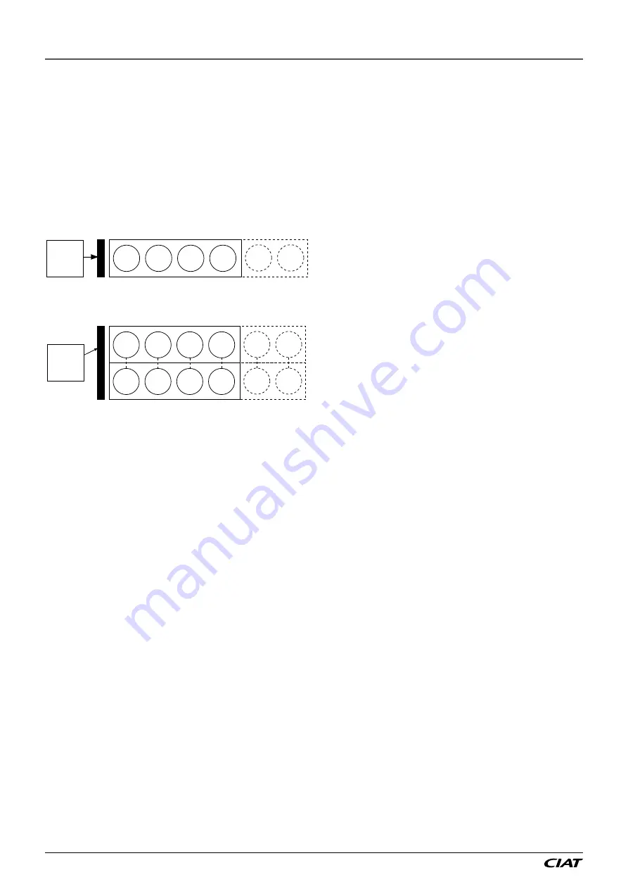
14.2.5.4 - Fan stage assignment
To ensure correct operation, a minimum of two stages is required.
Depending on the drycooler capacity the number of fans can be
between 2 and 8. They can be controlled by one fan or by linked
pairs, if necessary.
For example, a drycooler with 4 or 6 fans installed in series along
the length of the unit will result in a configuration of 4 or 6 fan
stages.
On the other hand, a drycooler with 8 or 12 fans arranged in
pairs along the length of the unit will also result in a configuration
of 4 or 6 fan stages.
Configuration with 4 and 6 stages (min. 2 - max. 8)
1
2
3
4
5
6
A
Fans linked in pairs -
4 and 6-stage configuration (min. 2 - max. 8)
1
2
3
4
5
6
A
1
2
3
4
5
6
Legend
A
Water inlet and outlet pipe side
1 to 6
Fans
14.2.5.5 -
Units without evaporator and condenser pump,
3-way valve configuration for low outside temperature
application
Units can be provided from the factory without evaporator and
condenser pump. If year-round low-temperature operation is
planned, the unit will be installed with a 3-way valve that is not
provided with the unit.
In this case Connect’Touch should be configured for 3-way valve
system control from an analogue 0-10 volt output on the master
board. An adequate condensing temperature will be maintained
with constant condenser flow rate. This configuration permits
year-round system operation down to -20°C outside temperatures.
Controlling and changing-over the fan stages, described in
chapter “Configuration of the number of fan stages and automatic
changeover of the fan stages” is identical.
14.2.5.6 -
Drycooler installation on units
When installing the drycooler, follow professional guidelines.
-
Water pipe sizing
-
Maximum piping and shut-off valve pressure drops based on
the available pressure of the unit pumps
-
Maximum drycooler elevation in relation to the unit (safety
valve at 4 bar on the unit water circuit).
-
Fan stage control (see “Fan stage control”).
-
Correct positioning of the outside air temperature and
drycooler outlet water temperature sensors.
14.2.6 -
LGN unit operation with a remote air-
cooled condenser
14.2.6.1 - Operating principle
LGN units have been specially designed to optimise the operation
of split installations, using air-cooled condensers as the chiller
heat rejection system. The installation of an operational system
is limited to the connection of the air-cooled condenser inlet and
outlet piping to the LGN unit.
The Connect Touch control system of the LGN includes a logic
to permit control the different fixed and variable-speed fan
variants.
14.2.6.2 -
Lead fan
The physical position of the air-cooled condenser with fixed or
variable-speed fans depends on the position of the leaving liquid
refrigerant manifold. In all cases there is always a so-called lead
fan. This is the fixed or variable-speed fan that is physically the
closest to the leaving liquid refrigerant manifold.
This ensures optimum subcooling on the condenser outlet side,
especially at part load. This is the first fan to start in each circuit
and the last fan to stop. A fan configuration with fixed-speed fans
permits year-round system operation down to 0°C outside
temperature.
A fan configuration with a variable-speed lead fan permits year-
round operation down to -10°C outside temperature.
14.2.6.3 - Communication to control the remote
condenser
The electronic board specifically integrated in the control box of
the remote condenser(by an option selection on the manufacturer
condenser) and a LEN communication BUS connected to the
microprocessor board of the unit are used for the overall system
control.
The option is supplied in the manufacturer condenser control
box. Connect the unit to board AUX1 in the condenser, using a
communication cable. The communication cable should be
connected to the plug with 3 points Wago type (5 mm spacing
or equivalent). The communication cable should be a shielded
type.
The option includes an air temperature sensor installed on the
condenser.
Connect Touch continuously optimises system operation to obtain
the best system efficiency by controlling the number of fans
required for any thermal load and outside temperature conditions.
14.2.6.4 -
Configuration of the number of fan stages and
fan type based on the air-cooled condenser model used in
the installation
Please refer to the instructions in the Connect Touch IOM units
to carry out the parameter setting of the air-cooled condenser
used in the installation:
-
Use of speed variation on the lead fan(s)
-
Number of fixed-speed fans
Based on the parameter setting used, the arrangement of the
digital and corresponding analogue outputs controlling the
fans will be activated by the control.
Connect Touch controls the automatic switching of all fan stages,
based on operating time and number of start-ups of the different
stages. This function prevents fan motors from only running a
little or not at all and the shafts seizing up, especially during
periods with a low cooling demand, when the outside temperature
is low. Switching is often specified by the condenser manufacturers
to ensure a long operating life of the fan motors that are only
used a little or not at all in these particular operating conditions.
14 - OPTIONS ET ACCESSORIES
Dynaciat LG/LGN
EN-58
Summary of Contents for DYNACIAT LG 080
Page 1: ...DYNACIAT LG LGN 07 2018 10188 Instruction manual...
Page 2: ...Dynaciat LG LGN EN 2...
Page 3: ...EN 3 Dynaciat LG LGN...
Page 67: ...EN 67 Dynaciat LG LGN...


