49
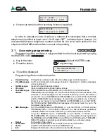
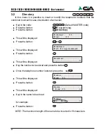
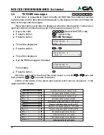
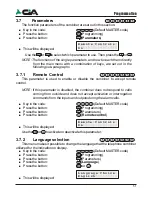
Key the delay with the keypad (for a maximum of 9999 seconds, equal to 2h 46'
39”) and press the
or
.
NOTE: If an event which overrides the cycle occurs during the delay period,
the delay timer is restarted, and any new activation will restart the
countdown from the beginning.
3.6
Outputs
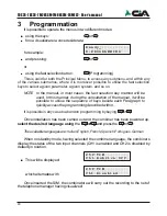
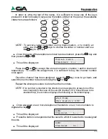
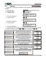
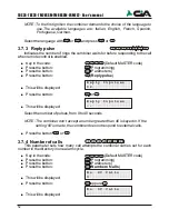
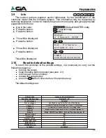
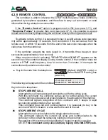
In this menu, it is possible to set the function parameters of the outputs, which are:
Mode, Reference Input, and Pulse Duration.
!
Key in the code:
(Default MASTER code)
!
Press the button:
(Programming)
!
Press the button:
(
Outputs
)
!
This will be displayed
Select output (from 1 at 2 for TDC26, TDC36, TM26GSM and to 1 at 6 for
ERMES2, TM66GSM) press the button
or
.After press the button
or
3.6.1
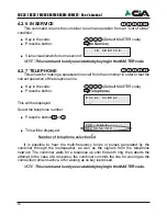
Mode
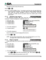
Once the output has been selected, it is necessary to set its behaviour when it
receives a command of activation or deactivation (see para 4.2.3).
!
This will be displayed
!
Press the button:
or
Use the
or
to select the “Mode” (see table below). Then press the
Or
.
6
O U T P U T
S E L E C T I O N
O u t
1
_
O u t
1
M o d e
ON command inverts the state of the output is this result disactive
and have not effect if result activated. In other way the OFF command
invert the output only if this result activated. For estimate the condition
of the output (if is activated or disactivated), the combiner fa reference at the condition
of the output same,or of the input of reference in agreement
to set up how much in the option “Input Refer.” (see par. 3.6.2).
The ON command generates an impulse on the output if this result disactivated
and have not effect if result activated. In other way the command OFF
invert the output only if this result activated.
Also in this modality the state of the escape (active or disactive)
depends from as the parameter for the income of reference
adopts a position. The difference regarding the previous modality consists
that the operation that comes executed is not that
one of the commutation, but is the generation of an impulse off-on-off, of the duration
set up in the parameter "Duration Impulse" (sees par. 3.6.3).
With this choice commandos ON and OFF have always the effect to invert
the state of the escape independently from its condition.
M o d e
O N / O F F
M o d e
I M P U L S E
M o d e
T O G G L E
Programmation
48
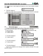
Once the condition under which the selected channel is alarmed has been
chosen, it is possible to choose whether or not to condition this input to
INT1, INT2
or
to
In K1, In K2.
.
“Conditioning”
an input means to make it depend on the presence of another
positive to make it operative; in the absence of this condition, the input is inoperative
or, if the condition becomes absent following the activation of the input, it causes the
current cycle to stop.
Example of programming of input
IN K1
for cycle activation or burglar alarm
conditioned by the connection of the control panel (+INT):
!
NO pulse with +INT active
The cycle of calls starts if the control panel is connected (INT active) and if it
is alarmed (IN K1 activated by the control panel alarm positive).
In this case, to stop the combiner's call cycle, it is sufficient to disconnect
the control panel from the local or remote.
!
NO pulse with inactive pulse
In this case, to stop the call cycle, operate the combiner or else wait for the
end of the cycles.
!
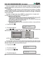
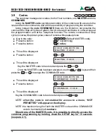
Press the button
!
This will be displayed:
Use the
or
to select which input (IN1; INT1; IN2; INT2 represented in the
table below) to use as
“Input INT”
. Then press the
or
NOTE: It is not possible to use
In K1
as “Input INT” of
channel 1
and
In K2
as
“Input INT” of
channel 2
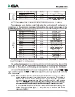
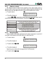
Once the input on which the function of the interrupted positive input depends has
been indicated for each channel, it is possible to insert a delay between the channel's
activation signal and the actual start of the call cycle
!
Press the button
!
This will be displayed:
!
Press the button
or
!
This will be displayed:
3 -
I N T
I n p u t
I N T 1
3 -
D e l a y
0 0 0 0
3 -
D e l a y
- - - -
I n t e r d e t t o
O f f
I n t e r d e t t o
I n
K 2
I n t e r d e t t o
I n
K 1
No condition
Input channel 1
Input channel 2
I n t e r d e t t o
I N T 2
I n t e r d e t t o
I N T 1
Input INT 1
Input INT 2
TDC26-TDC36-TM26GSM-TM66GSM-ERMES2- User’s manual

