


Programmable DC Power Supply 62000P Series Operating & Programming Manual
2. Use the numeric (
0
~
1
) keys or “Rotary” (
) knob to set the value.
3. Press
“
ENTER
” to confirm.
4. Press
“
EXIT
” to return to MAIN PAGE.
Clear Sequence has two options which are CLEAR SEQ. = YES / NO. The main function
of Clear Sequence is to clear the 10 sequences settings to program and reset them to factory
default as Figure 4-8 shows.
[ S E Q U E N C E ]
S E Q N O . = 1
S E Q .
T Y P E = A U T O
V O L T A G E = 0
V S . R .
= 1 . 0 ( V / m S )
C U R R E N T = 0
I
S . R .
= 1 . 0 ( A / m S )
T T L O U T = 0
< B I N A R Y = 0 0 0 0 0 0 0 0 >
T I M E = 0
▲
▼
Figure 4-8
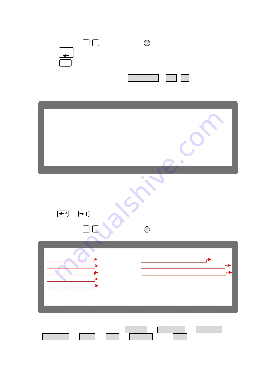
4.2 Setting
Sequence
1. Use
“
”, “
” keys to move the cursor to the column to be set as Figure 4-9
shows.
2. Use the numeric (
0
~
1
) keys or “Rotary” (
) knob to set the value.
[ S E Q U E N C E ]
S E Q N O . = 1
S E Q .
T Y P E = A U T O
V O L T A G E = 0
V S . R .
= 1 . 0 ( V / m S )
C U R R E N T = 0
I
S . R .
= 1 . 0 ( A / m S )
T T L O U T = 0
< B I N A R Y = 0 0 0 0 0 0 0 0 >
T I M E = 0
▲
▼
)
1
(
)
2
(
)
3
(
)
4
(
)
6
(
)
5
(
)
7
(
)
8
(
Figure 4-9
Each sequence has eight options: (1) SEQ NO., (2) SEQ. TYPE, (3) VOLTAGE, (4)
CURRENT, (5) V S_R, (6) I S_R, (7) TTL OUT, and (8) TIME. They are described
below.
4-8


