Installation and Setup
Mirage 4K35 User Manual
32
020-101377-03 Rev. 1 (07-2015)
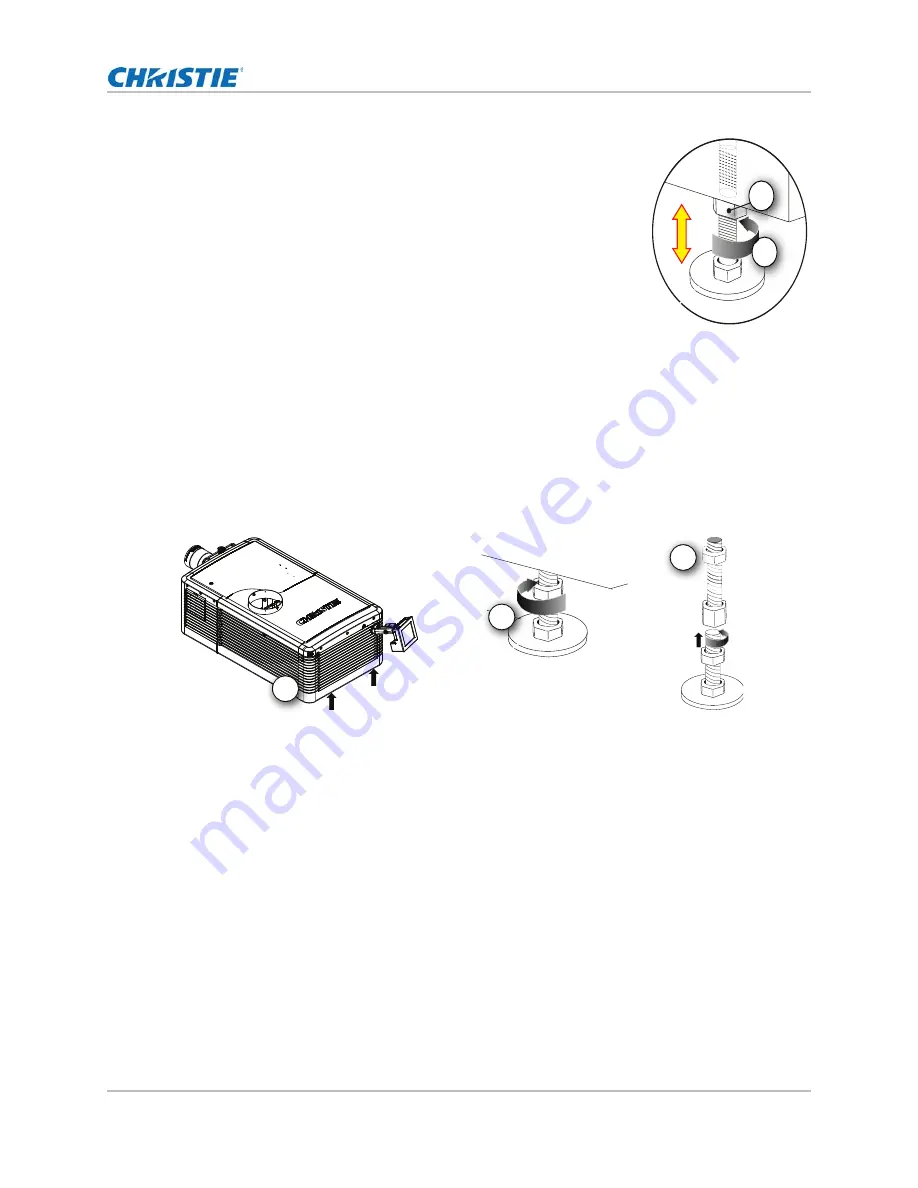
4. Once the required adjustment is made, tighten the lock nut
against the bottom of the projector (B).
The projector provides 4 inches of adjustment at the front and
11.5 inches of adjustment at the rear.
5. If the vertical or horizontal position of the projector requires more
adjustment than the standard feet allow, two 6-inch extension
rods can be installed to increase the amount of available
adjustment.
Install the foot extension rods
1. Elevate the rear of the projector to access the two rear feet.
2. Remove the feet by loosening the lock nut and rotating the each foot out of the projector.
3. Add the extension rods to the standard feet.
4. Thread the extended feet into the projector’s baseplate.
5. Adjust the feet until the required tilt is achieved.
6. Lock the feet in place by turning each lock nut until it fits tight against the projector.
Install the touch panel controller
1. Loosen the mounting arm just enough for the end to fit over the ball joint located on the rear
panel of the projector.
The touch panel controller (TPC) becomes loose from the mounting arm when the mounting
arm lock is loosened.
2. Tighten the mounting arm lock until it fits tightly on the joint.
The TPC safety strap comes installed on the projector ball point.
3. Connect the cable from the touch panel controller (TPC) to the connector on the rear panel of
the projector.
A
B
1
2
3


