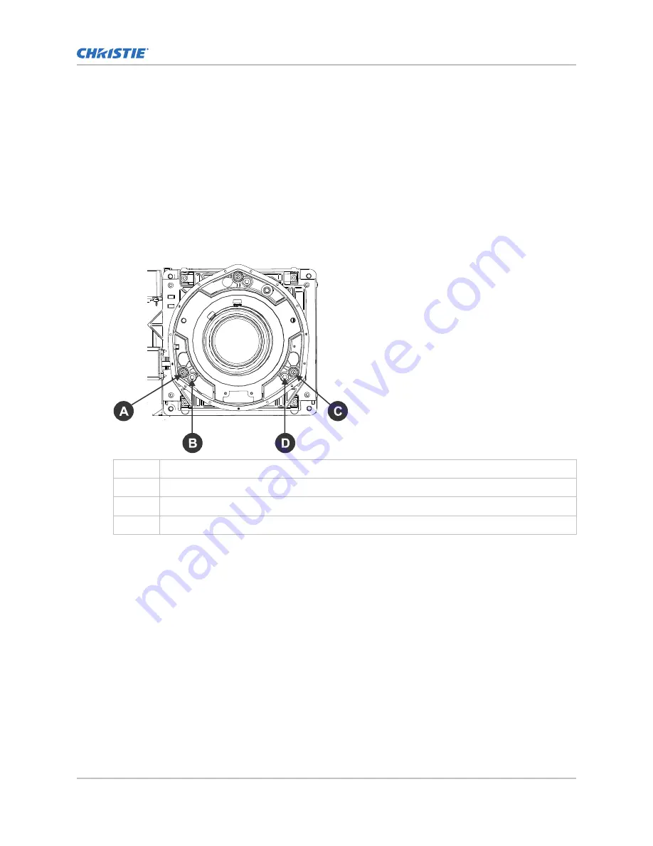
When adjusting boresight, you must maintain the boresight distance from the lens to the prism plane
set by Christie. For example, when you move the top screw outward, turn the bottom two boresight
screws to maintain the overall distance.
Only adjust horizontal boresight 1/8 of a turn or less at one time to maintain optimal lens performance
(factory setup of absolute lens distance to the prism). It is critical that you count each turn of the cap
screws to ensure accurate adjustment.
Ensure that the boresight lockdown screws are adequately tightened. Not adequately tightening the
boresight screws can result in excessive onscreen image vibration. After adjusting boresight, evaluate
the onscreen image vibration and re-adjust if needed.
1. Remove the lens surround.
2. Display the DC2K Boresight test pattern.
3. Loosen the right boresight set screw (B).
A
Right Boresight Cap Screw
B
Right Boresight Set Screw
C
Left Boresight Cap Screw
D
Left Boresight Set Screw
4. Turn the right boresight cap screw (A) 1/16 of a turn clockwise.
5. Adjust the left boresight cap screw (C) equally in the opposite direction.
6. If the quality of the projected image has not improved, turn the right boresight cap screw 1/16
of turn counter-clockwise. Make sure the left adjuster is adjusted equally in the opposite
direction.
7. Check the screen each time an adjustment is made. The right-side adjustments affect the top
right and bottom left points on the screen. Once both cross hairs are in focus, lock the set
screw for right boresight.
8. Repeat steps 5 to 7 for the left side.
9. Verify that each corner of the screen is equally in focus.
If this is not the case, repeat vertical boresight.
Adjusting the image
CP2308-G User Guide
54
020-102863-01 Rev. 1 (05-2018)
Copyright
©
2018 Christie Digital Systems USA, Inc. All rights reserved.
Summary of Contents for CP2308-G
Page 1: ...User Guide 020 102863 01 CP2308 G...
Page 98: ......


