background image

CM6SV65 and 83

Installation Instructions

4

ASSEMBLY AND INSTALLATION

Installation

CAUTION:

Tracks must be parallel. Small variations in

cabinet width will affect performance.

The lift tracks are designed to be mounted to the sides of the
cabinet through the prepunched holes in the base of the tracks.

IMPORTANT ! :

Allow adequate clearance around all moving

parts.

1.

Using screws of dequate length attach the motor drive side
track to left side of cabinet, keeping track even with front
edge of cabinet.

NOTE:

Top of track should be 1 1/2" below the location of the

top edge of the door panel when the panel is in the
open position.

2.

Using screws of dequate length attach the right side track to
right side of cabinet, keeping track even with front edge of
cabinet.

3.

Attach counterweight arms to the sides of the cabinet above
tracks. Hold the end of the arm with the lower wheel tight to
the top and with the notch tight against the back of the track.

NOTE:

The counterweight arms should extend 1/4" past the

front of the tracks.

IMPORTANT ! :

Use screws of adequate length.

4.

Attach counterweight cables to the wheel plates.

5.

Remove thumbnut from stud on wheel plate.

6.

Slide cable eye over threaded stud on wheel plate.

7.

Secure cable to the plate with thumbnut.

8.

Screw the door plates to back of moving door panel.

NOTE:

The plates are mounted 1/4" down from the top of the

panel with the notched corners to the top. Position the
alignment notches on either end of the plates even with
the edge of the panel.

IMPORTANT ! :

Before attaching door panel, make sure

wheel plates on left and right tracks are tight to track. If they are
not tight, loosen the red shipping screws in the center of the
plates, firmly push on outside of wheel plates, and retighten red
shipping screw.

9.

Remove hex nuts from the threaded studs on wheel plates.

10. Place adjustment slots in door plates over studs on wheel

plates, center door panel side to side on opening, and
secure with hex nuts.
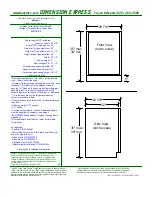
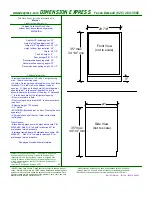
Figure 1

Summary of Contents for CM6SV65

Page 1: ...e protection against harmful interference in a residential installation This equipment generates uses and can radiate radio frequency energy and if not installed and used in accordance with the instructions may cause harmful interference to radio or television communications However there is no guarantee that the interference will not occur in a particular installation If this equipment does cause...

Page 2: ...ler s responsibility to make sure all components are properly assembled and installed using the instructions provided Read all instructions before using this furnishing DANGER TO REDUCE THE RISK OF ELECTRIC SHOCK ALWAYS unplug this furnishing from the electrical outlet before cleaning WARNING TO REDUCE THE RISK OF BURNS FIRE ELECTRIC SHOCK OR INJURY TO PERSONS Unplug from outlet before putting on ...

Page 3: ...e doors stop reverse run a few seconds and then stop again Auxiliary Controls There is an activator button located on the front of the motor box which will activate the doors Status Light The Status Light on the front of the Motor Box indicates the operating condition of the mechanism In normal operating conditions the status light will be solid green with the doors at rest and will blink a series...

Page 4: ...t to the top and with the notch tight against the back of the track NOTE The counterweight arms should extend 1 4 past the front of the tracks IMPORTANT Use screws of adequate length 4 Attach counterweight cables to the wheel plates 5 Remove thumbnut from stud on wheel plate 6 Slide cable eye over threaded stud on wheel plate 7 Secure cable to the plate with thumbnut 8 Screw the door plates to bac...

Page 5: ...Installation Instructions CM6SV65 and 83 5 Figure 2 ...

Page 6: ...of 12 wide x 3 4 thick flakeboard to 1 1 2 shorter than the length identified in step 3 IMPORTANT The weight of the panel MUST equal the combined weight of the counterweights Attaching and Testing The Counterweights 1 Secure mounting plate to counterweight with screws of adequate length 2 Remove thumbnut from stud on counterweight mounting plate 3 Slide cable eye over stud on the counterweight pla...

Page 7: ... just enough to give line of sight Two an IR sensor extension cord can be used to position the IR sensor in the cabinet near to the other remote controlled units For example near to the VCR or DVD player Install Light Dimmer Module Optional With the dimmer option installed cabinet lighting can be switched on or off or dimmed using the left buttons on the systems remote control To install the optio...

Page 8: ...ocations etc The system will then stop and remember these learned measurements Figure 8 System Controls and Indicators Learn Mode The CM6SV system has no limit switches The system uses an encoder on the motor to collect data and send it to the micro processor s memory The software learns about its environment speed time duration stop points etc during the initial setup of the unit and retains that...

Page 9: ...ar The Status Light will flash in groups of 5 red followed by a pause The motor is running but the doors are not moving Has the motor box been uncoupled from the track or is the motor box bent causing it to become uncoupled from the track Power Loss The Status Light will be on solid red There has been a power loss due to an electrical storm etc When next activated the doors will move at a slow spe...

Page 10: ...18 952 894 6918 Europe A Fellenoord 130 5611 ZB EINDHOVEN The Netherlands P 31 0 40 2668620 F 31 0 40 2668615 Asia Pacific A Room 30I Block D Lily YinDu International Building LuoGang BuJi Town Shenzhen CHINA Post Code 518112 P 86 755 8996 9226 8996 9236 8996 9220 F 86 755 8996 9217 8820 000019 2007 Chief Manufacturing www chiefmfg com 03 07 ...

Reviews: