Installation Instructions
CM6SV65 and 83
7
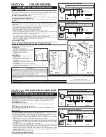
Figure 4
IR Sensor Placement
The placement of the IR sensor can be crucial to proper
operation of the system. A flexible IR sensor is provided to make
it easier to achieve reliable operation.
In most applications, the IR sensor may be installed on top of
the cabinet. However, tall ceilings and/or dark colored ceilings
can absorb the IR signal. If inconsistent operation is
encountered there are two alternatives.
•
One, the flexible IR sensor eye can be placed so that it
gives the sensor "line of sight" to the signal from the
remote controller. Often this merely involves placing the
IR sensor so that it peeks up over the top of the cabinet.
It doesn't have to be much, just enough to give "line of
sight".
•
Two, an IR sensor extension cord can be used to
position the IR sensor in the cabinet near to the other
remote controlled units. (For example, near to the VCR
or DVD player)
Install Light Dimmer Module (Optional)
With the dimmer option installed cabinet lighting can be
switched on or off or dimmed using the left buttons on the
systems remote control.
To install the optional dimmer:
1.
Plug 115VAC lighting into the back of the Light Dimmer
Module.
2.
Plug the other end of Dimmer Module cord into a 115VAC
grounded receptacle on motor assembly.
CAUTION:
The Dimmer is for 120 volt incandescent or
Halogen lamps of at least 25 watts and should not to exceed
300 watts total.
The system also provides the option of creating and saving two
different lighting "scenes". Please refer to the Remote Control
instructions for information on how to configure "scenes".
Figure 5
From Dimmer Module