background image

Page 44 


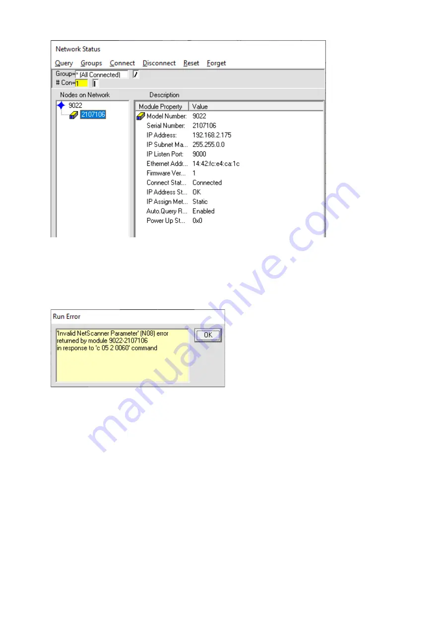
The FlightDaq-TL is only configured to output the primary data stream in 
NetScanner emulation mode. If NUSS is used in its default form, it will start up 
expecting the default run state which is 0. This will expect secondary and 
tertiary data so you therefore get the following error when the Run screen is 
selected. 


To overcome this, another scan list must be configured. To do this, right click 
on the module as before and select run states. The following window will 
appear with the default 0 scan list displayed. 
 

Summary of Contents for FlightDaq-TL

Page 1: ...lgate Road North Walsham Norfolk NR28 0AJ ENGLAND Tel 01692 500555 Fax 01692 500088 FlightDaq TL Multi Functional Scanner INSTALLATION AND OPERATING MANUAL e mail info chell co uk Visit the Chell webs...

Page 2: ...in this manual may impair the user s protection Chell Document No 900232 Issue 1 5 ECO 4559 Date 13th September 2021 Chell s policy of continuously updating and improving products means that this manu...

Page 3: ...ction 18 5 2 The Setup tab 19 5 3 Common Controls Sidebar 20 5 4 The Setup Parameters Page 21 5 4 1 Introduction 21 5 4 2 Data Streaming 21 5 4 3 General Ethernet Comms 22 5 5 Live Data Page 23 5 7 Th...

Page 4: ...Page 3 7 3 1 Changing the Power Mode of the device 48 7 3 2 Factory default procedure 48 7 4 Cleaning 49 Appendix 1 Channel Configurations 50...

Page 5: ...tric pressure transducer The FlightDaq TL can be configured for any combination of channels without comprising speed or performance with the exception of the 24V excitation which must be applied to al...

Page 6: ...A and B 2 2 Package Dimensions 241 2 x 89 x 68mm Weight 1 53 Kg 2 3 Ethernet Specifications TCP IP 10Mb s 100Mb s via Auto Negotiation TCP and UDP protocols supported 2 4 Operating conditions Operati...

Page 7: ...e 1 Remove all fourteen screws from the baseplate using a 2 0mm hex driver 2 Carefully remove the baseplate from the device to avoid damaging the gasket 3 Adjust DIP switch to required settings See ta...

Page 8: ...nection Type Lemo 1B series plug Part Number FXG 1B 308 XXXXXX plus strain relief Example part numer FDG 1B 308 CYBD52Z plus GMA 1B 045 RA strain relief Pin Number Function 1 Vs Secondary Input 2 24 V...

Page 9: ...uts which can be configured for four different ranges 78mV 300mV 5V and 10V In addition excitation can be provided on pin 1 for resistance and ratiometric ranges and pin 2 for 24 volts excitation In a...

Page 10: ...10V N A 5 N A Volts 300mV 78mV N A 6 N A Volts 300mV 300mV N A 7 N A Volts 300mV 5V N A 8 N A Volts 300mV 10V N A 9 05 or 00 Volts 5V 78mV N A 10 01 or 00 Volts 5V 300mV N A 11 06 or 00 Volts 5V 5V N...

Page 11: ...et to 78mV to measure the hot junction and the secondary input is set to 5V which when combined with the excitation will measure the output of the thermistor The results from the two inputs are conver...

Page 12: ...thermocouple is correct The heater is enabled via the web server and will apply a current to a heating resistor bonded to the cold junction for 15 seconds The user can then determine if the polarity...

Page 13: ...figured to measure resistance over a number of ranges as in the table below Configuration Number Type Code Type Variant Range Sub Range Excitation 25 30 Resistance 250R 300mV 1 k 26 31 Resistance 500R...

Page 14: ...s over a number of ranges as in the table below Conversion from resistance to temperature is carried out by using the in built NIST tables Configuration Number Type Code Type Variant Range Sec Range E...

Page 15: ...aq TL can be configured to measure RTD 385 pt100 using the four wire technique to remove the effect of lead resistance as below Configuration Number Type Code Type Variant Range Pri Range Sec Range Ex...

Page 16: ...fied The FlightDaq TL can be configured to measure a range of amplified pressure transducers These can have an excitation of 10V or 24V The FlightDaq TL can be configured for transducer output full sc...

Page 17: ...Exc SPARE 78mV 24V 38 105 Pressure Amplified Sub 300mV 24V Exc SPARE 300mV 24V 39 106 Pressure Amplified Sub 5V 24V Exc SPARE 5V 24V 40 107 Pressure Amplified Sub 10V 24V Exc SPARE 10V 24V 41 108 Pres...

Page 18: ...TL can be configured for transducer output full scales of 78mV 300mV 5V or 10V as below Configuration Number Type Code Type Variant Range Pri Range Sec Range Excitation 45 112 Pressure Ratiometric 78m...

Page 19: ...as of functionality namely Setup Live Data Channel Configuration Advanced and Factory Tools Setup provides the means to set FlightDaq TL s main operating parameters such as data streaming rates and de...

Page 20: ...Page 19 5 2 The Setup tab Figure 5 21 Main Setup page...

Page 21: ...ions Control Function RESET button Resets the FlightDaq TL similar to power cycling the device Use to activate new settings and or rebuild calibration tables The option exists for a hard reset and a s...

Page 22: ...e 5 41 Data Steaming Setup Control Function Comms Protocol radio button Chooses the communication protocol that is to be used This button changes what options are available below it Data Rate option l...

Page 23: ...2 TCP Comms group IP Address IP address allocated to FlightDaq TL on the user s network Subnet Subnet mask as set on the user s network Local port Local port of the device fixed to 101 Apply TCP Appli...

Page 24: ...layed on the page and updated at a rate of around 2Hz The type of value shown in the live data window may be selected by means of the option buttons in the righthand frame These are as follows Enginee...

Page 25: ...Page 24 Figure 5 52 Live Data Page Figure 5 53 Live Data Page...

Page 26: ...y tables The summary table appears at the top of the Channel Configuration tab and gives the user a quick summary of the current configuration of the primary channels as shown below in figure 5 72 Fig...

Page 27: ...onfiguration data resides This will always be internal unless Smart Lemo s are used When a Smart Lemo is used the configuration including any look up table s are stored within the Smart Lemo Config he...

Page 28: ...ge as a Transducer Type then the following range options will be available Secondary FSV Here the full scale of the secondary input is configured If you have selected a specific transducer type such a...

Page 29: ...l will appear as shown in Figure 5 74 below Figure 5 74 Channel Configuration with Smart Lemo As can be seen all settings stored to and therefore read from the Smart Lemo are identified with an asteri...

Page 30: ...ate Smart Lemo connected which enables the calibration for that transducer to be tied to and travel with that transducer 5 8 1 Standard In Built Look Up Tables The standard in built look up tables ava...

Page 31: ...tab as below Figure 5 81 Channel Configuration group It can be seen that in this case channel 2 is set to a transducer type of Voltage Under these circumstances the internal LUT editor is available a...

Page 32: ...values entered above into the LUT Remove last entry pair This will remove the last entry in the LUT 5 8 2 1 Loading a custom LUT from file A custom LUT can be loaded into the FlightDaq TL memory from...

Page 33: ...elect an appropriate file Then select Import and the file will be loaded into the FlightDaq TL as below Figure 5 83 Look up table editor This shows that file is loaded into the memory for the primary...

Page 34: ...red for a 5V input The LUT will convert voltage an engineering unit First enter the measured input value in this case volts and the output value in engineering units Figure 5 84 Look up table editor T...

Page 35: ...In this example an input value of 5V will result in a reading of 10 and an input value of 5V will result in a reading of 50 Any input values between the points in this table will be linearly interpola...

Page 36: ...formation is available together with the data from the transducer Smart Lemo connectors for voltages PRT s and Thermocouples are available from Chell To configure a channel for use with a Smart Lemo s...

Page 37: ...e correct channel LUT config is in view in the Lookup Table Config window and add remove entry pairs manually or clear import an LUT from a file in the same way as with standard custom LUTs see sectio...

Page 38: ...Page 37 5 9 Advanced Page The advanced tab contains extra options that users may find useful for more exact configuration but are not compulsory Figure 5 91 Advanced group...

Page 39: ...nning average filter The impulse filter is a three term median filter designed to remove any noise on the data The average filter is a running average filter Select the appropriate filtering the click...

Page 40: ...ps on the data packets If the timestamp is enabled it will have an effect on the maximum transmission rate Figure 5 95 Timestamp PTP synchronisation on checkbox This allows the user to select whether...

Page 41: ...ps if the user is not using PTP In the first box it will show the timestamp and in the second box it displays the timestamp converted date time to make it easier to understand NOTE the user has to cli...

Page 42: ...f the hardware trigger setting is requested as part of the c 00 command the FlightDAQ TL does not support a hardware trigger Transducer Heater Enable This is the function that allows the FlightDaq TL...

Page 43: ...around 2Hz Figure 5 97 Live health check group 5 9 6 Live Data Precision This section in the Miscellaneous tab allows the user to configure the precision of the measurements displayed in the Live Dat...

Page 44: ...es designed for the NetScanner products first enable the NetScanner emulation mode in the Advanced tab Click to enable NetScanner emulation and the enter the correct model type 9022 or 9146 Click Appl...

Page 45: ...p expecting the default run state which is 0 This will expect secondary and tertiary data so you therefore get the following error when the Run screen is selected To overcome this another scan list mu...

Page 46: ...Page 45 Select an additional Scan List in this case we have chosen 4...

Page 47: ...Page 46 Then disable the secondary and tertiary data streams...

Page 48: ...can the select Run first right click on the FlightDaq TL Acknowledge the two errors and then change the run state using the window below You will then be able to display the data from the FlightDAQ T...

Page 49: ...evice to avoid damaging the gasket 3 Adjust DIP switch to required settings See table below 4 Change the metal identifying tag on the side of the case to show the correct mode DC or PoE 5 Re insert th...

Page 50: ...g A dirty instrument may be wiped clean with a soft cloth that has been sprayed with a proprietary foaming cleaner then wiped dry immediately Under no circumstances should the instrument be wetted dir...

Page 51: ...8mV 5V 10k 20 14 Thermocouple K 78mV 5V 10k 21 15 Thermocouple N 78mV 5V 10k 22 16 Thermocouple R 78mV 5V 10k 23 17 Thermocouple S 78mV 5V 10k 24 18 Thermocouple T 78mV 5V 10k 25 30 Resistance 250R N...

Page 52: ...10V 10V 45 112 Pressure Ratiometric 78mV 10V 78mV 10V 10V 46 113 Pressure Ratiometric 300mV 10V 300mV 10V 10V 47 114 Pressure Ratiometric 5V 10V 5V 10V 10V 48 115 Pressure Ratiometric 10V 10V 10V 10V...

Reviews: