background image


EZrail™ RGBA User Manual 

Page 15 of 22 

4-Channel 

Channel 

Function 

Value 

Setting 


Red 

000 

ó

 255  0–100% 


Green 

000 

ó

 255  0–100% 


Blue 

000 

ó

 255  0–100% 


Amber 

000 

ó

 255  0–100% 


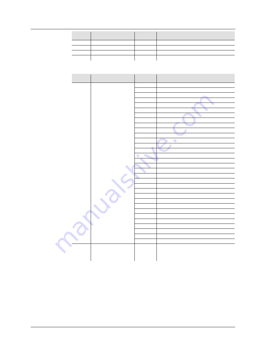
2-Channel 

Channel 

Function 

Value 

Setting 


Auto Programs 

000 

ó

 007  No Function 


008 

ó

 015  Red 


016 

ó

 023  Green 


024 

ó

 031  Blue 


032 

ó

 039  Amber 


040 

ó

 047  Cyan 


048 

ó

 055  Magenta 


056 

ó

 063  Yellow 


064 

ó

 071  White (RGB) 


072 

ó

 079  Red + Amber 


080 

ó

 087  Green + Amber 


088 

ó

 095  Blue + Amber 


096 

ó

 103  Red + Green + Amber 


104 

ó

 111  Red + Blue + Amber 


112 

ó

 119  Green + Blue + Amber 


120 

ó

 127  White (RGBA) 


128 

ó

 135  Auto Program 1 


136 

ó

 143  Auto Program 2 


144 

ó

 151  Auto Program 3 


152 

ó

 159  Auto Program 4 


160 

ó

 167  Auto Program 5 


168 

ó

 175  Auto Program 6 


176 

ó

 183  Auto Program 7 


184 

ó

 191  Auto Program 8 


192 

ó

 199  Auto Program 9 


200 

ó

 207  Auto Program 10 


208 

ó

 215  Auto Program 11 


216 

ó

 223  Auto Program 12 


224 

ó

 231  Auto Program 13 


232 

ó

 239  Auto Program 14 


240 

ó

 247  Auto Program 15 


248 

ó

 255  Sound-Active mode 


Speed/Sensitivity 

000 

ó

 255 

Auto programs speed 
(when Auto Programs is between 128–247) 
Sound sensitivity 
(when Auto Programs is between 248–255) 


Summary of Contents for EZrail RGBA

Page 1: ...User Manual ...

Page 2: ...ientation 10 Rigging 10 4 Operation 11 Control Panel Operation 11 Menu Map 11 Configuration DMX 12 Starting Address 12 EZrail RGBA Sections for DMX Control 12 DMX Channel Modes Assignments and Values 13 18 Channel 13 10 Channel 13 8 Channel 14 5 Channel 14 4 Channel 15 2 Channel 15 Configuration Standalone 16 Preset Programs including Sound Active Mode 16 Sound Sensitivity 16 Auto Program 17 Custo...

Page 3: ...f values 50 60 A set of values of which only one can be chosen Settings A menu option not to be modified Menu Settings A sequence of menu options to be followed ENTER A key to be pressed on the product s control panel ON A value to be entered or selected Symbols Symbol Meaning Critical installation configuration or operation information Not following these instructions may make the product not wor...

Page 4: ...re that the voltage of the outlet to which you are connecting the product is within the range stated on the decal or rear panel of the product The product is for indoor use only IP20 To prevent risk of fire or shock do not expose the product to rain or moisture Always install the product in a location with adequate ventilation at least 20 in 50 cm from adjacent surfaces Be sure that no ventilation...

Page 5: ... 5 of 22 2 INTRODUCTION Overview Back Panel View Display Safety Loop Power In Fuse Holder DMX Out DMX In Power Out Microphone Control Buttons Power Switch Battery Charged Green Indicator Light Battery Charging Red Indicator Light ...

Page 6: ...Page 6 of 22 EZrail RGBA User Manual Dimensions 19 9 in 505 mm 6 1 in 155 mm 2 9 in 73 mm ...

Page 7: ...eable lithium battery for cable free operation To charge the battery simply plug in the power cord at any time before during or after operation To charge the battery before or after operation with all the LEDs off leave the power switch in the Off position The red indicator light for the battery turns on while the battery is charging The green indicator light turns on when the battery is done char...

Page 8: ...e holder 3 Pry the fuse holder out of the housing 4 Remove the blown fuse from the holder 5 Replace with a fuse of the exact same type and rating 6 Insert the fuse holder back in place and reconnect power A spare fuse is not included however the safety cap has room for a spare Always replace a blown fuse with the same type and rating Installed fuse held by plastic clip Spare fuse holder inside saf...

Page 9: ...rail RGBA units on 120 VAC or up to 64 EZrail RGBA units on 230 VAC The power linking diagram shown above corresponds to the North American version of the product ONLY If using the product in other markets you must consult with the local CHAUVET distributor as power linking connectors and requirements may differ in your country or region 1 st Product 2 nd Product 3rd Product Additional Products ...

Page 10: ... elevated platform or a truss When rigging the product onto a truss you should use a mounting clamp of appropriate weight capacity The brackets have a 13 mm hole which is appropriate for this purpose When power linking multiple products you must always consider the length of the power linking cable and mount the products close enough for the cable to reach The bracket adjustment knobs allow for di...

Page 11: ...2 channel DMX mode 4 CH 4 channel DMX mode 5 CH 5 channel DMX mode 8 CH 8 channel DMX mode 10CH 10 channel DMX mode 18CH 18 channel DMX mode SLAv Slave mode SU_ _ SU 0 SU31 Sound sensitivity control Colr r 0 r255 Red 0 100 g 0 g255 Green 0 100 b 0 b255 Blue 0 100 A 0 A255 Amber 0 100 ir IRC functionality Pr _ _ Preset Programs Pr 1 Pr17 SP 1 SP99 SPFL Run speed slow to fast Fd 0 Fd99 Dimmer speed ...

Page 12: ...choose a starting address that is too high you could restrict the access to some of the product s channels The EZrail RGBA uses up to 18 DMX channels in its 18 channel DMX personality which defines the highest configurable address to 495 If unfamiliar with DMX download the DMX Primer from www chauvetlighting com To select the starting address do the following 1 Press MENU repeatedly until the desi...

Page 13: ... ó 255 0 100 10 Red 000 ó 255 0 100 3 11 Green 000 ó 255 0 100 12 Blue 000 ó 255 0 100 13 Amber 000 ó 255 0 100 14 Red 000 ó 255 0 100 4 15 Green 000 ó 255 0 100 16 Blue 000 ó 255 0 100 17 Amber 000 ó 255 0 100 18 Shutter 000 ó 255 0 100 10 Channel Channel Function Value Setting Section 1 Dimmer 000 ó 255 0 100 2 Red 000 ó 255 0 100 1 2 3 Green 000 ó 255 0 100 4 Blue 000 ó 255 0 100 5 Amber 000 ó ...

Page 14: ...ó 135 Auto Program 1 136 ó 143 Auto Program 2 144 ó 151 Auto Program 3 152 ó 159 Auto Program 4 160 ó 167 Auto Program 5 168 ó 175 Auto Program 6 176 ó 183 Auto Program 7 184 ó 191 Auto Program 8 192 ó 199 Auto Program 9 200 ó 207 Auto Program 10 208 ó 215 Auto Program 11 216 ó 223 Auto Program 12 224 ó 231 Auto Program 13 232 ó 239 Auto Program 14 240 ó 247 Auto Program 15 248 ó 255 Sound Active ...

Page 15: ...6 ó 103 Red Green Amber 104 ó 111 Red Blue Amber 112 ó 119 Green Blue Amber 120 ó 127 White RGBA 128 ó 135 Auto Program 1 136 ó 143 Auto Program 2 144 ó 151 Auto Program 3 152 ó 159 Auto Program 4 160 ó 167 Auto Program 5 168 ó 175 Auto Program 6 176 ó 183 Auto Program 7 184 ó 191 Auto Program 8 192 ó 199 Auto Program 9 200 ó 207 Auto Program 10 208 ó 215 Auto Program 11 216 ó 223 Auto Program 12 ...

Page 16: ... the dimmer speed options Fd 0 Fd99 slow to fast show on the display 6 Use UP or DOWN to select the desired dimmer speed for the preset program 7 Press ENTER and the strobe speed options FS 0 FS99 slow to fast show on the display 8 Use UP or DOWN to select the desired strobe speed for the preset program 9 Press ENTER Note With preset programs Pr16 and Pr 17 only the options for background color an...

Page 17: ...he display 9 Use UP or DOWN to select the desired strobe speed for the auto program 10 Press ENTER Custom Color Mixing To custom mix a color follow the instructions below 1 Press MENU repeatedly until Colr shows on the display 2 Press ENTER and one of the following colors shows on the display rXXX red gXXX green bXXX blue or AXXX amber 3 Press ENTER repeatedly to select the desired color 4 Use UP ...

Page 18: ...rol To choose a specific color with the IRC 1 Press MANUAL on the IRC 2 Press any number between 0 9 to choose your color 0 white RGBA 1 red 2 amber 3 yellow 4 green 5 cyan 6 blue 7 magenta 8 orange and 9 amber To manually control the RGB percentage 1 Press MANUAL on the IRC 2 Press R G or B to choose your color 3 Press or to increase or decrease the percentage of each color Miscellaneous Operatio...

Page 19: ... shows on the display 2 Press ENTER to accept 3 Connect the DMX input of the first slave unit to the DMX output of the master unit 4 Connect the DMX input of the subsequent slave units to the DMX output of the previous slave unit 5 Finish setting and connecting all the slave units Master unit 1 Set the master unit to operate in either a preset program including Sound Active mode 2 Make the master ...

Page 20: ...until the product is at room temperature Use a vacuum or dry compressed air and a soft brush to remove dust collected on the external surface vents and reachable internal components Clean all external optics and glass transparent surfaces with a mild soap solution ammonia free glass cleaner or isopropyl alcohol Apply the solution directly to a soft lint free cotton cloth or a lens cleaning tissue ...

Page 21: ... units 8 A 32 units 8 A 64 units Fuse T 1 A 250 V T 1 A 250 V Power I O US Worldwide UK Europe Power input connector IEC IEC Power output connector Edison IEC Power Cord plug Edison US Local plug Light Source Type Power Lifespan LED 0 25 W 100 000 hours Color Quantity Current Red 40 20 mA Green 40 20 mA Blue 40 20 mA Amber 40 20 mA Photo Optic Parameter Illuminance 2 m 805 lx Beam angle 15º Field ...

Page 22: ...number CHAUVET will refuse any product returned without an RMA number Write the RMA number on a properly affixed label DO NOT write the RMA number directly on the box Before sending the product clearly write the following information on a piece of paper and place it inside the box Name Address Phone number RMA number Description of the problem Be sure to pack the product properly Any shipping dama...

Reviews: