LT-WIC101010
Page 12 of 16
3
rd
Printing
3.7.3.
AC Voltage Connection
The WIC has a mounting location and a pair of conduit knockouts on the front for mounting a customer supplied AC load center.
3.7.4.
CTMS Operation
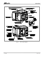
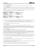
The four 6000W DC powered CTMS mounted on the sides of the WIC each have a fan speed controller and include two internal and two
external fans. The fans’ speed increases with increasing ambient temperature. Default fan settings are defined below and can be modified if
necessary.
The CTMS has a protective grate on the inside. This grate is secured in place by two bolts. To access the CTMS control panel, remove this
grate. For more information, refer to the heat exchanger documentation found inside the WIC.
Temperature range for cooling operations:
Parameter
Threshold
CTMS
Inside Temperature
< 77°F
Fans on
Inside Temperature
> 77°F
Fan Speed 25%
Inside Temperature
> 90°F
Fan Speed 100%
Temperature range for heating operations:
Parameter
Threshold
CTMS
Inside Temperature
< 50°F
Heating On
Inside Temperature
≥ 55°F
Heating Off
-
NOTE-
Changing the speed controller default factory set points can lead to system performance issues, such as equipment failures, increased power
use, unnecessary alarms, noise, condensation build up, fan failure caused by excessive runtimes and vibration.
Avoid placing items in front of the CTMS’s return and supply vents. Maintain a minimum of 2” clearance to enable proper air flow
.
The CTMS is shipped with the operational parameters set at the factory.
3.7.5.
IVS Operation
The DC powered IVS has an on-board controller, four ventilation fans, and six dampers leading into the WIC interior space.
The IVS is turned on in two ways. First, there is a manual timer that can be set for a maximum of one hour. A technician entering the WIC
can set this timer so that fresh air will be drawn into the WIC while work is being performed. Second, the IVS can be activated by an
internal temperature probe connected to the controller that turns the fans on when the interior temperature reaches 60⁰C. The IVS will then
draw outside air into the WIC to cool the cabinet.
3.7.6.
HVAC Operation
This section only applies if the 97-WIC10KHVACKT HVAC kit has been installed on the WIC.
The HVAC system is turned on manually whenever the WIC is occupied. The 10000BTU DC powered HVAC compressor and fans are
speed controlled. The compressor turns on at 30
°
C, reaches its high speed at 42
°
C, and turns off at 27
°
C. The internal fan is always on to
continually circulate heat within the cabinet. The heating cycle turns on at 10
°
C and off at 15
°
C. See the label on the air conditioner for
firmware information. For further information, refer to the HVAC documentation that ships with the kit.
-
NOTE-
Changing the cooling or heating cycles’ default factory set points can lead to system performance issues, such as equipment failures, increased
power use, unnecessary alarms, noise, condensation build up, compressor or fan failure caused by excessive runtimes and vibration.
Avoid placing items in front of the HVAC’s return and supply vents. Maintain a minimum of 2” clearance to enable proper air flow
.
3.7.7.
Fiber and Copper Entry
The WIC has two cable entry holes on the front (Ø1.5” and Ø1.0”) intended for conduit entry for the customer supplied AC load center.
The two sides and the rear each have a Ø1.06” entry hole for the ground cables.
The AC disconnect panel has three Ø7/8” knockouts intended to cable entry for the customer supplied Raycap AC disconnect. These holes
can be enlarged using a Greenlee tool to a maximum of Ø2.0”.
The upper rear corners, on the sides of the WIC, each have a sealed cable entry port for GPS cable entry.
The interior floor of the WIC has four entry ports for running cable inside from the runway space beneath the floor.


