LT-WIC101010
Page 10 of 16
3
rd
Printing
3.7.
WIC Wiring and Equipment
After the WIC is properly mounted in the desired location, apply No-Ox where bus bar and other 2-hole lug connections will be made.
Install ground and power connections. Always ground the equipment first, before making any other connections.
WARNING
Perform all bonding and grounding connections prior to any electrical and communications connections.
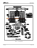
A basic electrical diagram is shown in Figure 11. This diagram shows the WIC with the power system, load center, and accessory kits
installed.
3.7.1.
Torque Requirements
Torque all hardware as shown below (unless otherwise noted). These values apply to SAE Grade 1 & 2 Low Carbon Steel, ASTM A307
Low Carbon Steel, and Stainless Steel Grade 18-8.
Thread
Size
In-lbs
Ft-lbs
4-40
4±10%
6-32
8±10%
8-32
16±10%
10-32
26±10%
12-24
50±10%
1/4-20/M6
60±5%
5±5%
5/16-18
125±5%
10.4±5%
3/8-16
180±5%
15.0±5%
1/2-13
500±2%
41.7±2%
5/8-11
1000±1%
83.3±1%
Use these values for the Grade 8 mounting hardware:
Thread
Size
Ft-lbs
Coarse
Fine
1/4
9
10
5/16
18
20
3/8
33
37
7/16
52
58
1/2
80
90
9/16
115
129
5/8
159
180
¾
282
315
7/8
454
501
1
682
764
3.7.2.
Ground Connection
The WIC has external ground bars on the sides and rear for grounding equipment. All cables entering the WIC must be grounded to the
2x12 position ground bars in the upper locations. The 24-position ground bars in the lower positions connect to the earth ground. Use the
pair of mounting studs on the external rear for connecting an earth ground. This requires a 3/8” lug with 0.75” spacing.
The equipment racks, as well as all equipment installed in the racks must be connected to the internal 46-position master ground bar,
located on the rear wall.
Use the pair of mounting studs on the external rear for connecting an earth ground. This requires a 3/8” lug with 0.75” spacing.


