LT-WIC101010
Page 8 of 16
3
rd
Printing
3.6.2.
Mounting the WIC on a Pad
Eight customer supplied, corrosion resistant, 3/4” Grade 8 hex head bolts with anchors are required for mounting the WIC to the concrete
pad. The WIC comes with a pair of washers for each mounting hole. Use both washers when securing the bolts. Use the following steps to
mount the WIC to a pad.
1.
Layout, drill, and set the 3/4” anchors per manufacturer’s recommendations. The embedment depth is not to exceed 3.5”.
2.
Clean any debris from the concrete pad.
3.
Ensure that the WIC is parallel to the pad surface as it is placed onto the pad and that it aligns with the holes in the pad.
4.
Place the WIC on the pad. Loosen the slings so that all the weight is on the pad. Check that the WIC is level and properly
aligned.
5.
Secure the WIC to the pad using the 3/4" hex head bolts and washers (two washers per bolt). Tighten all bolts securely.
6.
Once the WIC is secured, remove the slings and tagline and close the door.
3.6.3.
Mounting with the EMI Helical Mounting Kit
This kit is ordered separately from EMI (part number 1000-0000-0101).
1.
Assemble the universal driving tool on the correct Kelly bar adapter.
2.
Connect the Kelly bar adapter to the Kelly bar on the drive head.
3.
Move the drive tool assembly to the first helical and attach the universal
driving tool to the helical plate, ensuring that the Kelly bar is as centered in the
helical as possible. The leveling hardware can be used for this temporary
attachment.
4.
Lift the helical upright, allowing it to swing free of the ground.
5.
Maneuver the helical directly over the installation point.
6.
Lower the helical until the point of the helical is forced into the ground on
target.
7.
Screw the helical 12 inches into the ground and plumb using a level on two
sides at 90 degrees from each other.
8.
Continue screwing the helical into the ground while correcting the Kelly bar’s
orientation so the helical embeds itself straight. A ground man can be of
assistance in keeping the foundation plumb during the installation.
9.
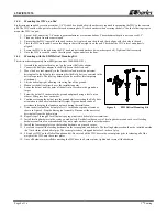
Drive the helical until the helical plate is 11 inches above grade, oriented as
shown in Figure 8. Stop the driving tool assembly. Disconnect the universal
driving tool from the helical plate.
10.
Repeat steps 3 through 9 for all helicals paying attention to helical plate orientations.
11.
Install leveling hardware in the center on each helical. Each helical has one set of leveling hardware and each set of leveling
hardware consists of one threaded rod, four nuts, eight washers, and four lock washers.
12.
Install the four corner plates on the leveling hardware, one in each corner.
13.
Level and secure all the leveling hardware on the corner plates and helicals. The leveling hardware should not be installed outside
the 3 inch radius of the helical pipe. The corner plates have elongated holes for 2 inches of play.
14.
Lift and set WIC on the Helical Foundation Kit. Be sure to bolt the WIC base to the corner plates prior to releasing all of the
weight of the WIC onto the corner plates.
15.
Once all hardware is installed connecting the WIC base to all corner plates, tighten and secure all the hardware.
Figure 8
EMI Helical Mounting Kit


