background image


LT-WIC101010 


3

rd

 Printing 

Page 9 of 16 


3.6.4.


Mounting with the EMI Gravity Mounting Kit 

This kit is ordered separately from EMI (part number 1000-0000-0162). 

Grade Considerations: 

1.


Ground/gravel should be normally dry and have good drainage. 

2.


Ground/gravel should be level or very close. 

Procedure: 

1.


Lift and set the WIC On The Ground (Gravity) Foundation Kit in the desired 
location. The WIC On The Ground (Gravity) Foundation Kit ships assembled, 
stairs separate of course, so lift and set it on grade in the desired location. If 
using a forklift and the forks are not long enough to get under all three bars of 
the frame, make sure the frame does not tilt over during lifting. This can be 
accomplished with weight on the two bars the forks did get under, or by 
removing the footers from the bar the forks did not get under. This is aimed at 
safety, as the frame can withstand tilting. The weight of the frame is 300 lbs. 
The weight of the footers are 31 lbs each. 

2.


Level the frame by adjusting the leveling hardware between the frame and the 
nine footers. Be sure to maintain 18 inches from grade to the top of the frame, 
which is the bottom of the WIC. Start by leveling the four corners first then adjust the remaining footers. 

3.


Lift and set the WIC on the WIC On The Ground (Gravity) Foundation Kit in desired location. Be sure to bolt the WIC base to 
the frame prior to releasing all of the weight of the WIC on the frame.  

4.


Once all hardware is installed connecting the WIC base to the frame, tighten and secure the hardware. 

3.6.5.


Mounting with the EMI Extension Mounting Kit 

This kit is ordered separately from EMI (part number D1007-0000-0012).  

This kit includes four concrete pad extensions for the four corners of the WIC. 

1.


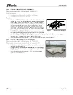
Set the four concrete pad extensions on the four corners of the concrete pad in 
the desired locations (Figure 10). 

2.


Lift and set the WIC on the extensions. Ensure that the WIC is level, and bolt 
the WIC base to the extensions prior to releasing all of the weight of the WIC 
on the extensions. 

3.


Once all hardware is installed connecting the WIC base to the extensions, 
tighten and secure the hardware. 


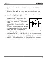
Figure 9 

EMI Gravity Mounting Kit 

Figure 10 

EMI Extension Mounting Kit 

Summary of Contents for WIC-101010SXAN1

Page 1: ...13 6 WARRANTY CUSTOMER SERVICE 13 7 SPECIFICATIONS 13 7 1 Regulatory Specifications 13 7 2 Product Specifications 14 7 3 Part Numbers 14 7 4 Alarm Connections 15 1 GENERAL INTRODUCTION 1 1 Document Pu...

Page 2: ...all connect to an interior master ground bar Equipment and power racks are added to the WIC by Worldwide Technologies See their documentation for information about the power equipment included Accesso...

Page 3: ...LT WIC101010 3rd Printing Page 3 of 16 Figure 3 WIC External Components...

Page 4: ...LT WIC101010 Page 4 of 16 3rd Printing Figure 4 WIC Internal Components Front and Right Side Walls Hidden...

Page 5: ...LT WIC101010 3rd Printing Page 5 of 16 Figure 5 WIC with Optional Kits and Equipment Racks Installed Front and Right Side Walls Hidden...

Page 6: ...serious damage s to persons or product Only authorized trained personnel shall install the WIC 3 3 Obtaining Tools and Equipment Obtain the following recommended or needed items for installing the WIC...

Page 7: ...ng to local practices including safety helmets and steel toed shoes Do not operate thehoisting equipment until all stabilizer are extended and in firm contact with the ground or adequate support struc...

Page 8: ...t the helical upright allowing it to swing free of the ground 5 Maneuver the helical directly over the installation point 6 Lower the helical until the point of the helical is forced into the ground o...

Page 9: ...ling hardware between the frame and the nine footers Be sure to maintain 18 inches from grade to the top of the frame which is the bottom of the WIC Start by leveling the four corners first then adjus...

Page 10: ...0 10 32 26 10 12 24 50 10 1 4 20 M6 60 5 5 5 5 16 18 125 5 10 4 5 3 8 16 180 5 15 0 5 1 2 13 500 2 41 7 2 5 8 11 1000 1 83 3 1 Use these values for the Grade 8 mounting hardware Thread Size Ft lbs Coa...

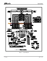
Page 11: ...LT WIC101010 3rd Printing Page 11 of 16 Figure 11 Electrical Diagram...

Page 12: ...this timer so that fresh air will be drawn into the WIC while work is being performed Second the IVS can be activated by an internal temperature probe connected to the controller that turns the fans o...

Page 13: ...the GFCI duplex receptacle periodically to ensure it is working The unit meets UL 943 which requires an auto monitoring self testing feature A flashing or solid red LED indicates a fault If the unit c...

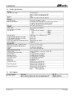
Page 14: ...97 WIC10KHVACKT kit Dantherm 708349 48VDC Cooling Capacity 10000BTU Environmental Operating Temp Range Outside Enclosure 40 to 115 F 40 to 46 C Operating Temp Range Inside Enclosure 40 to 131 F 40 to...

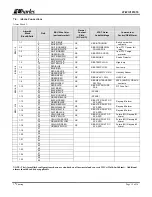
Page 15: ...12 1 9 17 RED BROWN NC RBS GEN TRANSFER SW FAIL 350A 48VDC CB AUX contacts 18 BROWN RED 1 10 19 RED SLATE NC RBS FIF PDU FUSE FAIL FIF Fuse Fail 20 SLATE RED 1 11 21 BLACK BLUE SPARE 22 BLUE BLACK 1 1...

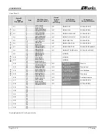
Page 16: ...RFA MULT 14 ORANGE RED 2 8 15 RED GREEN NC RBS BATT TEMP HIGH DC PLANT HITEMP1 16 GREEN RED BBU 25 28 2 9 17 RED BROWN SPARE 18 BROWN RED 2 10 19 RED SLATE SPARE 20 SLATE RED 2 11 21 BLACK BLUE SPARE...

Reviews: