


13- 11- 605
Page 49
SECTION 10
TROUBLE SHOOTING AUTO SENTRY
R
--W CONTROLLER
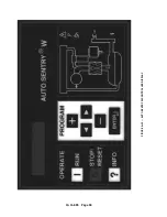
DISPLAY MODES
A green power on light is located in the lower right corner of the keypad. It lights whenever the controls are energized.
A steady light indicates that automatic restarting is not enabled, the compressor must be restarted manually follow-
ing a power failure. A blinking green light indicates that the control will automatically resume its selected mode fol-
lowing an interruption in power.
The normal display indicates the package service pressure, the airend discharge temperature, the total running
hours, and one of the following operating modes. The green run light will be on for any operating mode, whether
the compressor is running or not.
READY
The compressor has been stopped by pressing the [STOP/RESET] key.
CON
The compressor is operating in the Constant Run mode.
LDM
The compressor is operating in the Low Demand mode.
AUTO
The compressor is operating in the Automatic mode.
SEQ n
The compressor is operating in the Sequence mode.
The following alternate displays may be called by pressing the [ ? ] or a cursor [<] or [>] key. The [?] key always
displays DIF PRES on the first press; the cursor keys will redisplay the last alternate display. Any will scroll through
the list with additional presses.
DIF PRES
The pressure drop across the water filter
RES PRES
The pressure in the water reservoir
INJ PRES
The pressure between the filter and injectors
SYS PRES
The pressure at the service connection
DIS TMP
The temperature at the airend discharge
TOT HRS
The total hours of compressor running
LOAD HRS
The hours of compressor delivery
BD TMR
The time remaining before a blowdown will be allowed
AUTO TMR
The time remaining of unloaded motor operation
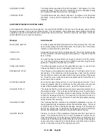
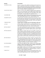
ADVISORY TROUBLE SHOOTING GUIDE
All advisories are indicated on the keypad by a yellow indicator in the Status area, and one of the following messages
alternating with the normal lower line display. Perform service or maintenance as indicated, the clear the advisory
as instructed in Section 4.
Message
Action Needed
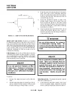
CHNG AIR FILTER
Excessive vacuum has been detected after the air filter, indicating it has
become full. Change the air filter to ensure maximum air delivery.
CHNG H
2
O FILTER
The differential pressure across the water filter has risen to over 30 psid.
Change the filter to ensure an adequate flow of coolant.
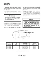
RELUBE
The unit has been operated for the programmed number of hours since
the last lubricant change or addition. Change or add lubricant as indicated
in the lubrication instructions to ensure lubricant quality.
Summary of Contents for ROTORCHAMP RCOF20
Page 13: ...13 11 605 Page 4 FIGURE 1 6 AIR WATER SCHEMATIC 300EWC797 B Ref Drawing ...
Page 16: ...13 11 605 Page 7 DECALS 206EAQ077 300EWC077 301EWC077 211EAQ077 207EAQ077 ...
Page 17: ...13 11 605 Page 8 DECALS 216EAQ077 206EWD077 222EAQ077 221EAQ077 208EAQ077 ...
Page 31: ...13 11 605 Page 22 FIGURE 4 2 FLOW CHART FOR SET UP PROGRAMMING 300EWC1255 Ref Drawing ...
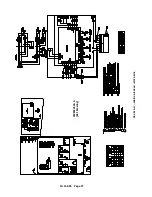
Page 41: ...13 11 605 Page 32 FIGURE 4 6 CONTROL TUBING SCHEMATIC 300EWC797 B Ref Drawing ...
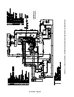
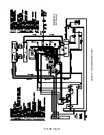
Page 45: ...13 11 605 Page 36 FIGURE 4 10 WIRING DIAGRAM FULL VOLTAGE 301EWC546 A Ref Drawing ...
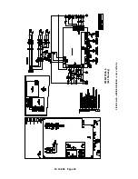
Page 46: ...13 11 605 Page 37 FIGURE 4 11 WIRING DIAGRAM WYE DELTA 302EWC546 A Ref Drawing ...
Page 47: ...13 11 605 Page 38 FIGURE 4 12 AUTO SENTRY W CONTROLLER DISPLAY ...
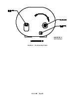
Page 49: ...13 11 605 Page 40 FIGURE 5 1 OIL LEVEL SIGHT GLASS 306EWC797 A Ref Drawing ...
Page 50: ...13 11 605 Page 41 FIGURE 5 2 FLOW DIAGRAM AIR COOLED 300EWC797 A Ref Drawing ...


