


13- 11- 605
Page 17
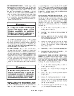
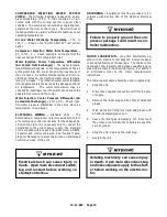
Operation at excessive discharge air
pressure can cause personal injury or
damage to equipment. Do not adjust
the full discharge air pressure above
the maximum stamped on the unit
nameplate.
8.
Operating Mode
-- Refer to Section 4 for detailed
information on the control system.
9.
Enclosure
-- Check for damaged panels or doors.
Check all screws and latches for tightness. Be
sure doors are closed and latched.
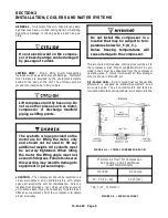
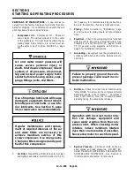
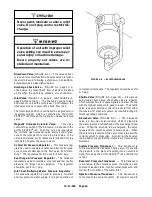
STARTING THE UNIT
-- It is a good practice to prime
the compressor air end and separator/reservoir prior to
initial start-- up following the installation of the compres-
sor package and following a manual draining of the wa-
ter reservoir. Pour 2 to 3 gallons of water in through the
inlet valve to prime the unit.
Start the unit by pushing the [RUN] key. The unit will
reach normal operating temperature in approximately
5 minutes. Check the package operating information
by pressing the [INFO] key or keypad cursor [<][>] keys
at any time during compressor operation.
DAILY CHECK
-- Refer to Section 8, “Maintenance
Schedule,” page 45.
STOPPING THE UNIT
-- Press [STOP/RESET] key.
The air/water reservoir will automatically blow down as
the motor stops.
Summary of Contents for ROTORCHAMP RCOF20
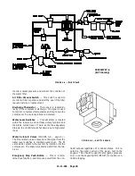
Page 13: ...13 11 605 Page 4 FIGURE 1 6 AIR WATER SCHEMATIC 300EWC797 B Ref Drawing ...
Page 16: ...13 11 605 Page 7 DECALS 206EAQ077 300EWC077 301EWC077 211EAQ077 207EAQ077 ...
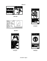
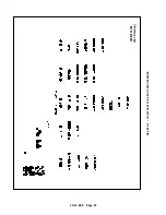
Page 17: ...13 11 605 Page 8 DECALS 216EAQ077 206EWD077 222EAQ077 221EAQ077 208EAQ077 ...
Page 31: ...13 11 605 Page 22 FIGURE 4 2 FLOW CHART FOR SET UP PROGRAMMING 300EWC1255 Ref Drawing ...
Page 41: ...13 11 605 Page 32 FIGURE 4 6 CONTROL TUBING SCHEMATIC 300EWC797 B Ref Drawing ...
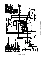
Page 45: ...13 11 605 Page 36 FIGURE 4 10 WIRING DIAGRAM FULL VOLTAGE 301EWC546 A Ref Drawing ...
Page 46: ...13 11 605 Page 37 FIGURE 4 11 WIRING DIAGRAM WYE DELTA 302EWC546 A Ref Drawing ...
Page 47: ...13 11 605 Page 38 FIGURE 4 12 AUTO SENTRY W CONTROLLER DISPLAY ...
Page 49: ...13 11 605 Page 40 FIGURE 5 1 OIL LEVEL SIGHT GLASS 306EWC797 A Ref Drawing ...
Page 50: ...13 11 605 Page 41 FIGURE 5 2 FLOW DIAGRAM AIR COOLED 300EWC797 A Ref Drawing ...


