


13- 11- 605
Page 23
6.
In the top line, “
BLOWDOWN TIME
” is displayed.
The bottom line will indicate a time between 1 and
20 minutes. It is factory set at 10 minutes. This
is the minimum time interval between blowdowns.
A longer blowdown time minimizes wasteful
dumping of compressed air when loading is likely
to occur in a short time.
7.
In the top line, “
AUTO TIME
” is displayed. The
bottom line will indicate a time between 5 and 20
minutes. It too, is factory set at 10 minutes. Its
function is to prevent too frequent motor starting,
and to allow the motor a ‘cool-- down’ period before
stopping.
8.
In the top line, “
REMOTE STOP
” is displayed.
The bottom line indicates either “TIMED” or “IM-
MEDIATE”. Refer to the description of “Remote
On/Off” later in this section for additional details.
Select the desired response to the remote input
and press [ENTER] to proceed.
9.
This completes the operational adjustments. The
controller will return to the main adjustments
menu.
Maintenance Adjustments
1.
If any service advisories are in effect (yellow AD-
VISORY indicator is on), they will be displayed on
the top line. The bottom line indicates “
LEAVE
ADVISORY
” (do not reset) or “
CLEAR ADVISO-
RY
” (turn it off). Select the desired action and
press [ENTER] to proceed.
2.
The top line displays “
NEXT RELUBE
” and the
hours remaining are displayed on the bottom line.
Press the [+] or [-- ] keys to switch to the lubrication
change interval (see UNIT SETUP) if service was
performed early. Press [ENTER] to proceed.
3.
This completes the maintenance adjustments.
The controller will return to the main adjustments
menu.
Sequence Adjustments
See “SEQUENCING COMPRESSORS WITH THE
AUTO SENTRY
R
-- W, page 25, for more details on set-
ting up and optimizing a sequenced compressor instal-
lation.
1.
In the top line, “
NUM OF SEQ UNITS
” is dis-
played. The bottom line will indicate a number in
the range of one through eight. This will be factory
set at “1”. This should be set to a number corre-
sponding to the number of compressors that are
currently installed on this air system that also have
AUTO SENTRY
R
-- W controllers. It should be
noted that all AUTO SENTRY
R
-- W compressors
on the system must have the same number pro-
grammed here to operate correctly in SE-
QUENCE mode. Adjust as required, and press
[ENTER] to proceed.
Setting the value in step 1 to one indi-
cates that no sequencing is to take
place. Consequently, steps 2, 3, and
4, which relate to sequencing, are
skipped by the AUTO SENTRY
R
--W;
the controller will return to the main
adjustments menu.
2.
In the top line, “
UNIT NUMBER
” is displayed. The
bottom line will again indicate a number of one
through eight and be factory set at “1”. Each
AUTO SENTRY
R
-- W in a sequenced system
must have a unique number here. The sequence
mode will not function if two or more compressors
have the same UNIT NUMBER. The most effi-
cient machine-- to-- machine communications will
occur when the lowest possible numbers are
used. Example: 1, 2, and 3 for a three compressor
installation.
This is the only setting which must be different for
each unit in a sequenced system. All other set-
tings should normally be the same for all units.
3.
In the top line, “
TRANSFER INTERVAL
” is dis-
played. The bottom line will indicate a number of
hours in the range of 1 to 5000. It is factory set at
24. This is the number of hours that this machine
will stay in the role of “master” or ”lead” compres-
sor.
Normally it is desirable to set this to the same val-
ue on all sequenced units to equalize running
hours. Different values may be programmed, if
desired, to help equalize hours.
4.
In the top line, “
LAG START DELAY
” is displayed.
The bottom line will indicate a number in the range
of 15 to 600 seconds. It is factory set at 30. This
is the length of time this machine will wait before
starting when the pressure drops below the load
point. This should be set to the same value for all
sequenced units. Its setting will depend on the
amount of air storage volume in the system. Too
small a number will result in more compressors
being started than is necessary to satisfy the de-
mand.
Summary of Contents for ROTORCHAMP RCOF20
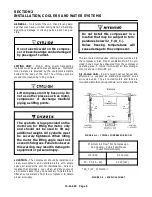
Page 13: ...13 11 605 Page 4 FIGURE 1 6 AIR WATER SCHEMATIC 300EWC797 B Ref Drawing ...
Page 16: ...13 11 605 Page 7 DECALS 206EAQ077 300EWC077 301EWC077 211EAQ077 207EAQ077 ...
Page 17: ...13 11 605 Page 8 DECALS 216EAQ077 206EWD077 222EAQ077 221EAQ077 208EAQ077 ...
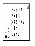
Page 31: ...13 11 605 Page 22 FIGURE 4 2 FLOW CHART FOR SET UP PROGRAMMING 300EWC1255 Ref Drawing ...
Page 41: ...13 11 605 Page 32 FIGURE 4 6 CONTROL TUBING SCHEMATIC 300EWC797 B Ref Drawing ...
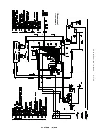
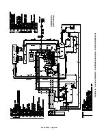
Page 45: ...13 11 605 Page 36 FIGURE 4 10 WIRING DIAGRAM FULL VOLTAGE 301EWC546 A Ref Drawing ...
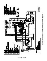
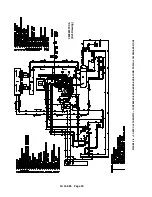
Page 46: ...13 11 605 Page 37 FIGURE 4 11 WIRING DIAGRAM WYE DELTA 302EWC546 A Ref Drawing ...
Page 47: ...13 11 605 Page 38 FIGURE 4 12 AUTO SENTRY W CONTROLLER DISPLAY ...
Page 49: ...13 11 605 Page 40 FIGURE 5 1 OIL LEVEL SIGHT GLASS 306EWC797 A Ref Drawing ...
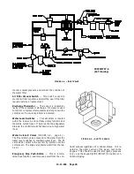
Page 50: ...13 11 605 Page 41 FIGURE 5 2 FLOW DIAGRAM AIR COOLED 300EWC797 A Ref Drawing ...


